Defining a Three-Phase Current Transformer and Its Common Scenarios
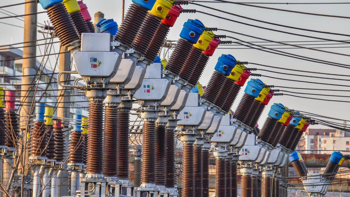
A Three Phase Current Transformer is an instrument transformer designed to measure electrical current within a three-phase power system. This device effectively reduces high primary currents to a much lower, standardized secondary current, typically 1A or 5A. This scaled-down current allows for safe and accurate measurement by meters and protective relays, which can then operate without a direct connection to high-voltage lines.
The global market for the Current Transformer is projected to grow significantly, reflecting its increasing importance in modernizing electrical grids.

Note: This growth underscores the critical role of the Three Phase Current Transformer. These devices are essential for ensuring the stability and efficiency of power distribution networks worldwide.
Key Takeaways
- A Three-Phase Current Transformer (CT) measures electricity in three-phase power systems. It changes high currents into smaller, safer currents for meters and safety devices.
- CTs work using magnets. High current in the main wire creates a magnetic field. This field then makes a smaller, safe current in another wire for measurement.
- CTs are important for three main reasons: they help accurately bill for electricity, protect equipment from damage during power surges, and allow smart systems to monitor power use.
- When choosing a CT, consider its accuracy for billing or protection, match its current ratio to your system's needs, and pick a physical type that fits your installation.
- Never leave a CT's secondary circuit open. This can create very high voltage, which is dangerous and can damage the equipment.
How a Three-Phase Current Transformer Works
A Three Phase Current Transformer operates on fundamental principles of electromagnetism to achieve its function. Its design is simple yet highly effective for safely monitoring powerful electrical systems. Understanding its internal workings reveals why it is a cornerstone of power grid management.
Core Operating Principles
The operation of a current transformer is governed by electromagnetic induction, a principle described by Faraday's Law. This process allows for current measurement without any direct electrical connection between the high-voltage primary circuit and the measurement instruments. The entire sequence unfolds in a few key steps:
- A high primary current flows through the main conductor (the primary coil).
- This current generates a corresponding magnetic field within the transformer's iron core.
- The magnetic core guides this changing magnetic field to the secondary coil.
- The magnetic field induces a much smaller, proportional current in the secondary coil.
- This secondary current is then safely fed to meters, relays, or control systems for measurement and analysis.
For three-phase applications, the device contains three sets of coils and cores. This construction enables the simultaneous and independent measurement of current in each of the three phase wires.
Construction and Key Components
A current transformer consists of three primary parts: the primary winding, the secondary winding, and a magnetic core.
- Primary Winding: This is the conductor carrying the high current that needs to be measured. In many designs (bar-type CTs), the primary is simply the main system busbar or cable passing through the center of the transformer.
- Secondary Winding: This consists of many turns of smaller-gauge wire wrapped around the magnetic core. It produces the reduced, measurable current.
- Magnetic Core: The core is a critical component that concentrates and directs the magnetic field from the primary to the secondary winding. The material used for the core directly impacts the transformer's accuracy and efficiency.
The choice of core material is essential for minimizing energy loss and preventing signal distortion. High-precision transformers use specialized materials to achieve superior performance.
| Material | Key Properties | Advantages | Common Applications |
|---|---|---|---|
| Silicon Steel | High magnetic permeability, low core loss | Cost-effective, mature manufacturing | Power transformers, current transformers |
| Amorphous Metal | Non-crystalline structure, very low core loss | Excellent energy efficiency, compact size | High-frequency transformers, precision CTs |
| Nanocrystalline Alloys | Ultra-fine grain structure, extremely low core loss | Superior efficiency, excellent high-frequency performance | High-precision CTs, EMC filters |
| Nickel-Iron Alloys | Very high magnetic permeability, low coercive force | Excellent linearity, great for shielding | High-precision current transformers, magnetic sensors |
Note on Accuracy: In the real world, no transformer is perfect. Errors can arise from several factors. The excitation current needed to magnetize the core can cause phase and magnitude deviations. Likewise, operating the CT outside its rated load, especially at very low or high currents, increases measurement error. Magnetic saturation, where the core can no longer handle more magnetic flux, also leads to significant inaccuracies, particularly during fault conditions.
The Importance of the Turns Ratio
The turns ratio is the mathematical heart of a current transformer. It defines the relationship between the current in the primary winding and the current in the secondary winding. The ratio is calculated by dividing the rated primary current by the rated secondary current.
Current Transformer Ratio (CTR) = Primary Current (Ip) / Secondary Current (Is)
This ratio is determined by the number of wire turns in each coil. For example, a CT with a 400:5 ratio will produce a 5A current on its secondary side when 400A flows through the primary conductor. This predictable step-down function is fundamental to its purpose. It transforms a dangerous, high current into a standardized, low current that is safe for measurement devices to handle. Selecting the correct turns ratio to match the system's expected load is crucial for ensuring both accuracy and safety.
Three-Phase vs. Single-Phase Current Transformers
Choosing the right current transformer configuration is essential for accurate and reliable power system monitoring. The decision between using a single Three Phase Current Transformer unit or three separate single-phase CTs depends on the system's design, the application's goals, and physical constraints.
Key Structural and Design Differences
The most apparent difference lies in their physical construction and how they interact with the conductors. A single-phase CT is designed to encircle a single electrical conductor. In contrast, a three-phase CT can be a single, consolidated unit that all three phase conductors pass through, or it can refer to a set of three matched single-phase CTs. Each approach serves a distinct purpose in power monitoring.
| Feature | Three Separate Single-Phase CTs | Single Three-Phase CT Unit |
|---|---|---|
| Physical Arrangement | One CT is installed on each phase conductor. | All three phase conductors pass through one CT window. |
| Primary Purpose | Provides accurate, phase-by-phase current data. | Detects current imbalances, primarily for ground faults. |
| Typical Use Case | Metering and monitoring of balanced or imbalanced loads. | Ground fault protection systems (zero sequence). |
Application-Specific Advantages
Each configuration offers unique benefits tailored to specific needs. Using three separate single-phase CTs provides the most detailed and accurate view of the system. This method allows for precise measurement of each phase, which is critical for:
- Revenue-Grade Billing: High-accuracy monitoring requires a dedicated CT on each phase to ensure fair and precise energy billing.
- Imbalanced Load Analysis: Systems with multiple single-phase loads (like a commercial building) often have unequal currents on each phase. Separate CTs capture this imbalance accurately.
A single-unit three-phase CT, often used for residual or zero-sequence measurement, excels at detecting ground faults by sensing any net difference in current across the three phases.
When to Choose One Over the Other
The choice depends heavily on the electrical system's wiring and the monitoring objective.
For applications demanding the highest accuracy, such as revenue-grade metering or monitoring systems with potentially imbalanced loads like solar inverters, using three CTs is the standard. This approach eliminates guesswork and prevents inaccurate readings that can occur when power is not consumed or produced equally on all phases.
Here are some general guidelines:
- Three-Phase, 4-Wire Wye Systems: These systems, which include a neutral wire, require three CTs for complete accuracy.
- Three-Phase, 3-Wire Delta Systems: These systems lack a neutral wire. Two CTs are often sufficient for measurement, as stated by Blondel's Theorem.
- Balanced vs. Unbalanced Loads: While a single CT's reading can be multiplied on a perfectly balanced load, this method introduces errors if the load is imbalanced. For equipment like HVAC units, dryers, or subpanels, always use a CT on each energized conductor.
Ultimately, considering the system type and accuracy requirements will lead to the correct CT configuration.
When Is a Three-Phase Current Transformer Used?
A Three Phase Current Transformer is a foundational component in modern electrical systems. Its applications extend far beyond simple measurement. These devices are indispensable for ensuring financial accuracy, protecting expensive equipment, and enabling intelligent energy management across industrial, commercial, and utility sectors.
For Accurate Energy Metering and Billing
Utilities and facility managers rely on precise energy measurements for billing. In large-scale commercial and industrial settings, where electricity consumption is substantial, even minor inaccuracies can lead to significant financial discrepancies. Current transformers provide the necessary precision for this critical task. They scale down high currents to a level that revenue-grade meters can safely and accurately record.
The accuracy of these transformers is not arbitrary. It is governed by strict international standards that ensure fairness and consistency in electricity metering. Key standards include:
- ANSI/IEEE C57.13: A standard widely used in the United States for both metering and protection current transformers.
- ANSI C12.1-2024: This is the primary code for electricity metering in the U.S., defining accuracy requirements for meters.
- IEC Classes: International standards like IEC 61869 define accuracy classes such as 0.1, 0.2, and 0.5 for billing purposes. These classes specify the maximum permissible error.
Note on Power Quality: Beyond just current magnitude, these standards also address phase angle error. Accurate phase measurement is crucial for calculating reactive power and power factor, which are increasingly important components of modern utility billing structures.
For Overcurrent and Fault Protection
Protecting electrical systems from damage is one of the most critical functions of a current transformer. Electrical faults, such as short circuits or ground faults, can generate immense currents that destroy equipment and create serious safety hazards. A complete overcurrent protection system works together to prevent this.
The system has three main parts:
- Current Transformers (CTs): These are the sensors. They constantly monitor the current flowing to protected equipment.
- Protective Relays: This is the brain. It receives the signal from the CTs and decides if the current is dangerously high.
- Circuit Breakers: This is the muscle. It receives a trip command from the relay and physically disconnects the circuit to stop the fault.
CTs are integrated with different types of relays to detect specific problems. For example, an Overcurrent Relay (OCR) trips when the current exceeds a safe level, protecting equipment from overloads. An Earth Fault Relay (EFR) detects current leaking to the ground by measuring any imbalance between the phase currents. If a CT saturates during a fault, it can distort the signal sent to the relay, potentially causing the protection system to fail. Therefore, protection-class CTs are designed to remain accurate even under extreme fault conditions.
For Intelligent Load Monitoring and Management
Modern industries are moving beyond simple protection and billing. They now use electrical data for advanced operational insights and predictive maintenance. Current transformers are the primary data source for these intelligent systems. By clamping non-intrusive CTs onto a motor's power lines, engineers can acquire detailed electrical signals without disrupting operations.
This data enables a powerful predictive maintenance strategy:
- Data Acquisition: CTs capture the raw line current data from operating machinery.
- Signal Processing: Specialized algorithms process these electrical signals to extract features that indicate the machine's health.
- Smart Analysis: By analyzing these electrical signatures over time, systems can create a "digital twin" of the motor. This digital model helps predict developing issues before they cause a failure.
This analysis of CT data can identify a wide range of mechanical and electrical problems, including:
- Bearing faults
- Broken rotor bars
- Air-gap eccentricity
- Mechanical misalignments
This proactive approach allows maintenance teams to schedule repairs, order parts, and avoid costly unplanned downtime, transforming the current transformer from a simple measurement device into a key enabler of smart factory initiatives.
How to Select the Right Three-Phase CT
Selecting the correct Three Phase Current Transformer is essential for system reliability and accuracy. Engineers must consider the application's specific needs, including accuracy requirements, system load, and physical installation constraints. A careful selection process ensures optimal performance for metering, protection, and monitoring.
Understanding Accuracy Classes
Current transformers are categorized into accuracy classes for either metering or protection. Each class serves a distinct purpose, and using the wrong one can lead to financial loss or equipment damage.
- Metering CTs provide high precision for billing and load analysis under normal operating currents.
- Protection CTs are built to withstand high fault currents, ensuring protective relays operate reliably.
A common mistake is using a high-precision metering CT for protection. These CTs can saturate during a fault, which prevents the relay from receiving an accurate signal and tripping the circuit breaker in time.
| Feature | Metering CTs | Protection CTs |
|---|---|---|
| Purpose | Accurate measurement for billing and monitoring | Operate protective relays during faults |
| Typical Classes | 0.1, 0.2S, 0.5S | 5P10, 5P20, 10P10 |
| Key Characteristic | Precision under normal loads | Survival and stability during faults |
Note on Over-Specification: Specifying an unnecessarily high accuracy class or capacity can dramatically increase cost and size. An oversized CT may be difficult to manufacture and nearly impossible to fit inside standard switchgear, making it an impractical choice.
Matching the CT Ratio to System Load
The CT ratio must align with the electrical system's expected load. A properly sized ratio ensures the CT operates within its most accurate range. A simple method helps determine the correct ratio for a motor:
- Find the motor's full load amperes (FLA) from its nameplate.
- Multiply the FLA by 1.25 to account for overload conditions.
- Choose the closest standard CT ratio to this calculated value.
For example, a motor with an FLA of 330A would require a calculation of 330A * 1.25 = 412.5A. The closest standard ratio would be 400:5. Selecting a ratio that is too high will reduce accuracy at low loads. A ratio that is too low can cause the CT to saturate during faults, compromising protection systems.
Choosing the Right Physical Form Factor
The physical form of a three-phase current transformer depends on the installation environment. The two main types are solid-core and split-core.
- Solid-core CTs have a closed loop. Installers must disconnect the primary conductor to thread it through the core. This makes them ideal for new construction where power can be shut off.
- Split-core CTs can be opened and clamped around a conductor. This design is perfect for retrofitting existing systems because it does not require a power shutdown.
| Scenario | Best CT Type | Reason |
|---|---|---|
| New hospital construction | Solid-core | High accuracy is needed, and wires can be safely disconnected. |
| Office building retrofit | Split-core | Installation is non-disruptive and does not require a power outage. |
Choosing between these types depends on whether the installation is new or a retrofit and if interrupting power is an option.
A three-phase current transformer is a critical device for safely measuring current in three-phase systems. Its primary applications ensure accurate energy billing, protect equipment by detecting faults, and enable intelligent energy management. Proper selection based on accuracy, ratio, and form factor is essential for reliable and safe system operation.
Looking Ahead: Modern CTs with smart technology and modular designs are making power systems more efficient. However, their effectiveness always depends on correct selection and safe installation practices.
FAQ
What happens if a CT secondary is left open?
An open secondary circuit creates a serious hazard. It induces an extremely high voltage across the secondary terminals. This voltage can damage the transformer's insulation and poses a severe risk to personnel. Always ensure the secondary circuit is shorted or connected to a load.
Can one CT be used for both metering and protection?
It is not recommended. Metering CTs require high accuracy at normal loads, while protection CTs must perform reliably during high fault currents. Using a single CT for both purposes compromises either billing accuracy or equipment safety, as their designs serve different functions.
What is CT saturation?
Saturation occurs when a CT's core cannot handle more magnetic energy, typically during a large fault. The transformer then fails to produce a proportional secondary current. This leads to inaccurate measurements and can prevent protective relays from operating correctly during a critical event.
Why are secondary currents standardized to 1A or 5A?
Standardizing secondary currents at 1A or 5A ensures interoperability. It allows meters and relays from different manufacturers to work together seamlessly. This practice simplifies system design, component replacement, and promotes universal compatibility across the electrical industry. 🔌
See Also
Innovative Current Transformers: Unveiling Smart Metering's Next-Gen Solutions
Essential Power Transformer Selection: A Novice's Comprehensive Guide
Boosting Metering Precision: The Role of Manganin Copper Shunts
Delving Into Molybdenum High-Temperature Furnaces: Design and Operational Insights
Top 5 Applications: Optimizing Single Stage Rotary Vane Vacuum Pumps