Cylindrical Gears Explained A 2026 Beginner's Guide
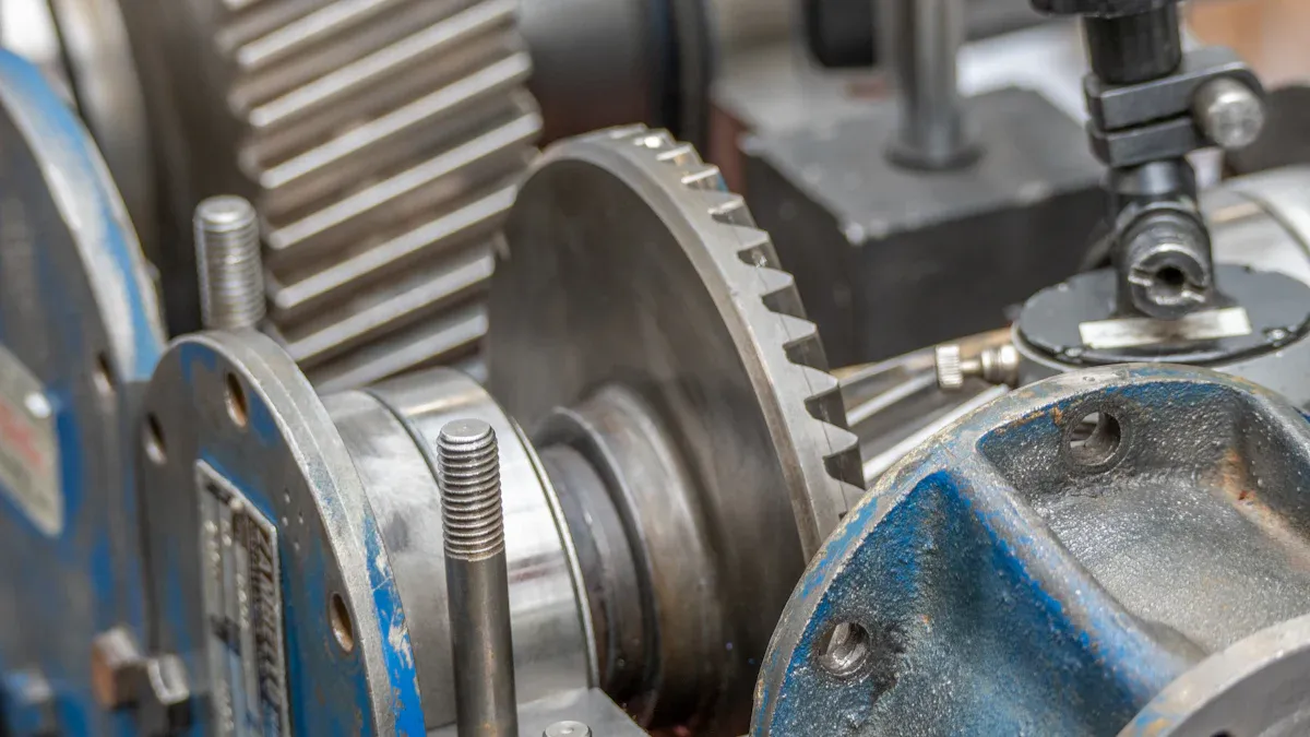
Cylindrical gears are special toothed wheels. They transmit power and motion between parallel shafts. The main job of a gear is to change a machine's speed, torque, or direction. A common type is the spur gear.
Did You Know? ⚙️ You can find these fundamental components in countless machines. They are in car transmissions and large industrial equipment.
Key Takeaways
- Cylindrical gears are toothed wheels. They move power and motion between shafts. They change a machine's speed, power, or direction.
- Spur gears are common and simple. Helical gears are quieter and stronger. Double helical gears remove side push.
- Choosing the right gear material and heat treatment makes gears last longer. This helps them work better.
How Do Cylindrical Gears Work?
Cylindrical gears operate on a simple yet brilliant mechanical principle. They transfer motion and energy when the teeth of one gear push against the teeth of another. This interaction, called meshing, allows for the precise control of speed, power, and direction in a machine. Let's explore the details of how this happens.
The Principle of Meshing Teeth
At its core, gear operation relies on the shape of the teeth. Most modern gears use a special curve called an involute profile. This design is crucial for smooth and consistent motion.
The fundamental law of gearing explains this. It states the common normal of the teeth must pass through a fixed point. This ensures the gears rotate at a constant velocity ratio. The involute profile helps gears achieve this.
- Constant Velocity: Involute teeth maintain a steady speed ratio, even if the distance between the gear centers varies slightly.
- Line of Action: The contact point between meshing teeth moves along a straight path, called the line of action. This ensures smooth force transmission.
- Conjugate Action: The tooth shapes are designed to satisfy this fundamental law, resulting in predictable and reliable motion.
Precision Matters: Understanding Backlash Backlash is the small gap or "play" between meshing teeth. It is the amount of lost motion when a gear changes direction. While a tiny amount is needed for lubrication, too much backlash reduces a system's precision. Several factors can increase backlash:
- Runout: Variations in a gear's roundness.
- Pitch Deviation: Inconsistent spacing between teeth.
- Pressure Angle Deviation: Errors in the angle of the tooth face.
Transmitting Power and Torque
Gears do more than just transfer motion; they are force multipliers. They transmit power by converting an input speed and torque into a different output speed and torque.
Torque is the rotational force a gear can apply. When a motor turns a small gear (the driving gear), it exerts a tangential force on the teeth of a larger gear (the driven gear). This force, acting at a distance from the gear's center, creates torque. The relationship can be understood with a simple formula.
| Variable | Description |
|---|---|
M1, M2 | Torque of driving and driven gear |
Ft1 | Tangential force |
d1, d2 | Reference diameter of driving and driven gear |
z1, z2 | Number of teeth of driving and driven gear |
The efficiency of this power transmission depends heavily on the gear tooth geometry. Well-designed tooth profiles reduce friction and distribute loads evenly. This minimizes energy loss and improves the overall performance of the cylindrical gears.
Understanding Gear Ratios
The gear ratio is the heart of a gear system's function. It defines the relationship between the driving gear and the driven gear. You can calculate this ratio easily. Just divide the number of teeth on the driven gear by the number of teeth on the driving gear.
Gear Ratio = Number of Teeth on Driven Gear / Number of Teeth on Driving Gear
This ratio directly controls the trade-off between speed and torque.
- Increasing Torque: When a small gear drives a large gear, the output speed decreases, but the output torque increases. This is a "high" gear ratio.
- Increasing Speed: When a large gear drives a small gear, the output speed increases, but the output torque decreases. This is a "low" gear ratio.
In a compound gear train, multiple gears are mounted on the same shaft. This setup allows engineers to create very large gear ratios in a compact space. The final ratio is determined by the number of teeth on the first and last gears in the train.
Real-world machines use this principle everywhere. For example, the worm gears in car windshield wipers use a high ratio to turn motor speed into powerful, slow sweeps. Automatic car transmissions use complex planetary gear systems to provide a range of different ratios for efficient driving.
Exploring the Main Types of Cylindrical Gears
Cylindrical gears come in several designs. Each type offers unique advantages for specific jobs. The choice of gear depends on factors like speed, load, noise, and cost. Understanding the main types helps engineers build better and more efficient machines.
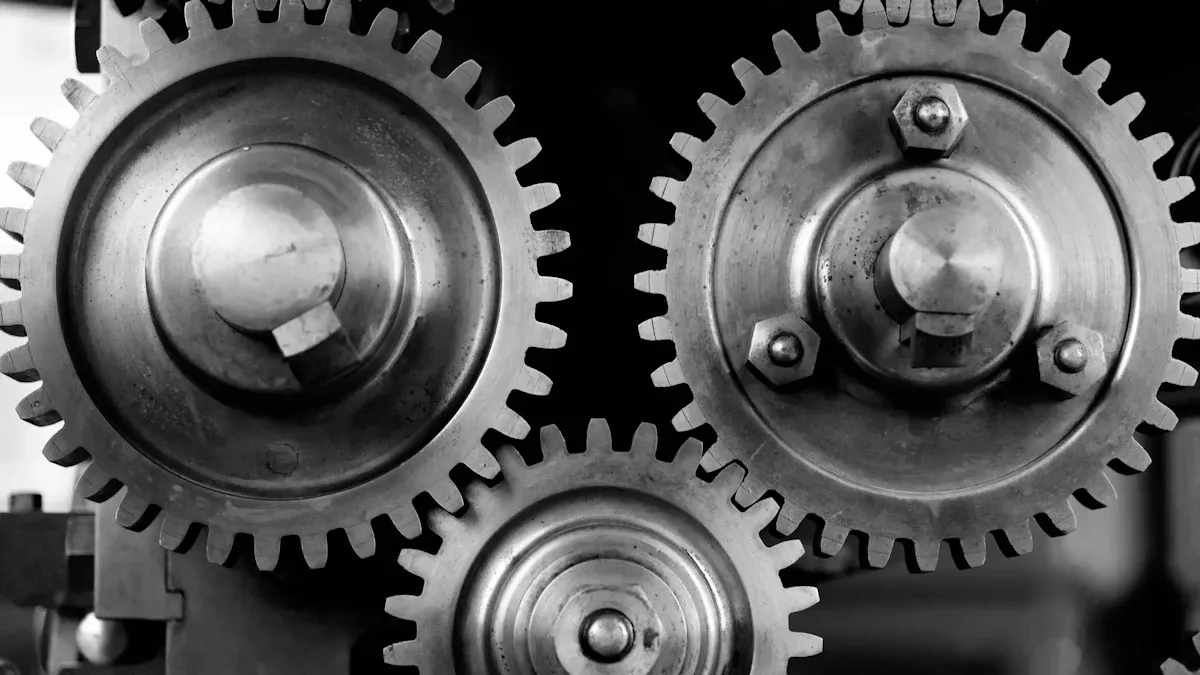
Spur Gears
Spur gears are the most common and basic type of gear. They have straight teeth cut parallel to the gear's axis of rotation. Their simple design makes them easy to manufacture and cost-effective.
Spur gears mesh one tooth at a time. This creates an abrupt transfer of load, which can be noisy at high speeds. However, they are highly efficient. A well-designed and lubricated spur gear system can achieve a power transmission efficiency between 98% and 99%. This efficiency drops below 95% without proper lubrication due to increased friction.
Spur Gear Failure Under Heavy Loads High stress can cause spur gears to fail. Understanding these failure modes is key to designing durable systems.
- Bending Fatigue: Repeated loading can cause a crack to form at the tooth's root. The crack grows slowly until the tooth breaks off.
- Contact Fatigue (Pitting): Repeated stress on the tooth surface leads to tiny cracks and pits. This can range from fine micropitting (a frosted look) to larger macropitting.
- Wear: Material is removed from the tooth surface. This can be caused by metal-to-metal contact (adhesion) or by contaminants in the lubricant (abrasion).
- Scuffing: This is a severe form of adhesion. Metal welds and tears between teeth, causing a rough surface and rapid failure.
Helical Gears
Helical gears represent an improvement over spur gears for many applications. Their teeth are cut at an angle to the gear's axis, forming a helix. This angled design changes how the teeth engage.
Instead of an abrupt contact, helical teeth engage gradually. The contact starts at one end of the tooth and spreads across its face as the gear rotates. This leads to several key benefits.
- Smoother and Quieter Operation: The gradual engagement reduces impact and vibration. Helical gears can run 8-15 dB quieter than similar spur gears.
- Higher Load Capacity: The load is distributed across multiple teeth at once. This reduces stress on any single tooth, allowing the gear to handle higher loads and last longer.
- Efficient Power Transmission: The longer contact time between teeth results in efficient power transfer, typically in the range of 94%-98%, even at high speeds.
A major consideration with helical gears is the creation of axial thrust. The angled teeth produce a force that pushes the gear along its shaft. This requires special bearings, like thrust or angular contact bearings, to manage the load.
| Helix Angle Range | Noise Reduction Benefit | Thrust Load Impact | Bearing Requirement |
|---|---|---|---|
| 15-25° | Optimal (8-15 dB quieter) | Moderate | Standard (up to 20°), then specialized |
| 20-35° | Good load distribution | Increased (25° angle creates 47% thrust) | Requires thrust or angular contact bearings |
| Above 30° | Less noise benefit | Significantly increased | Requires robust thrust bearing combination |
Double Helical and Herringbone Gears
Double helical gears solve the axial thrust problem. They are essentially two helical gears placed side-by-side with opposite helix angles. One set of teeth pushes in one direction, while the other set pushes in the opposite direction. These forces cancel each other out, eliminating the net axial thrust.
A herringbone gear is a type of double helical gear where the two halves are joined in the middle, forming a distinctive 'V' shape. This design is very strong and ideal for high-torque applications.
Manufacturing Challenges The complex geometry of double helical gears makes them difficult and expensive to produce. Key challenges include:
- Precise Alignment: The two opposing helices must be perfectly aligned. Any error can reintroduce stress and vibration.
- Complex Tooling: Manufacturing requires specialized machines. For herringbone gears, there is no gap in the middle for the cutting tool to exit, adding another layer of complexity.
Because of their smooth power transmission and high load capacity, these gears are vital in heavy industry. You can find them in:
- Marine Propulsion Systems: For driving ship propellers.
- Power Generation: In steam and gas turbines.
- Heavy Machinery: Driving cement mills, steel rolling mills, and mining equipment.
- Oil and Gas Industry: In powerful pumps and drilling rigs.
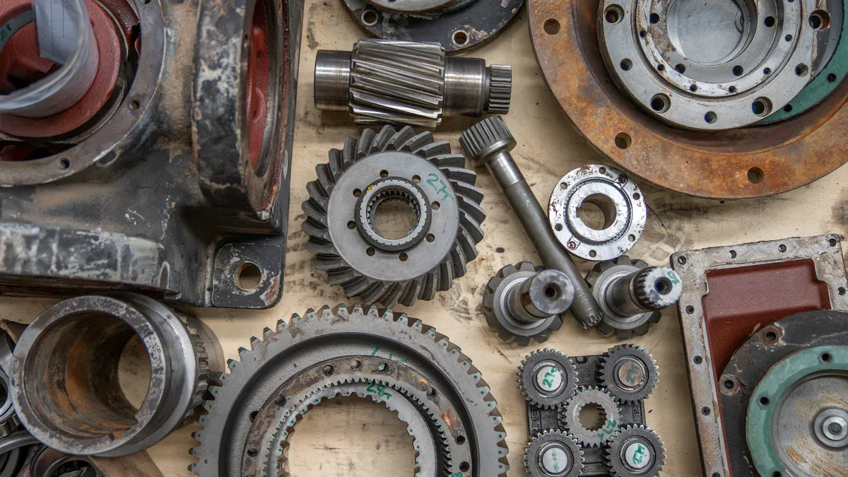
Choosing the Right Material
The performance and lifespan of all cylindrical gears depend heavily on their material. The choice involves balancing strength, wear resistance, corrosion resistance, and cost. Heat treatment processes are also used to enhance a material's properties.
Common materials include steel alloys, cast iron, and bronze.
| Material Family | Type | Key Properties & Uses |
|---|---|---|
| Iron Alloys | Carbon Steel | Inexpensive and easy to machine. Good for general-purpose gears. |
| Alloy Steel | Stronger and more wear-resistant than carbon steel. Used for high-load, high-stress applications. | |
| Stainless Steel | Excellent corrosion resistance. Ideal for food processing or marine environments. | |
| Cast Iron | Good wear resistance and vibration damping. Often used in industrial machinery. | |
| Copper Alloys | Phosphor Bronze | High wear resistance and low friction. Excellent for worm wheels that mesh with steel worms. |
| Aluminum Bronze | Superior strength and corrosion resistance compared to other bronzes. Handles very high loads. |
Heat treatment dramatically improves a gear's durability. Two common surface hardening processes are carburizing and nitriding. They create a very hard outer surface (case) while keeping the inner material (core) tough and ductile.
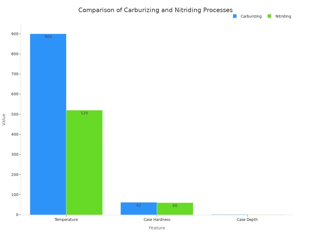
- Carburizing adds carbon to the steel's surface at high temperatures. It creates a very hard, deep case, making it ideal for gears that face high impacts and heavy loads.
- Nitriding uses nitrogen and lower temperatures. It produces less distortion, making it perfect for precision gears where maintaining tight tolerances is critical. It also improves corrosion resistance.
Cylindrical gears are essential for transmitting power between parallel shafts. Spur gears offer simple efficiency, while helical gears provide quieter operation for higher speeds and loads. Selecting the correct gear type and material is critical for meeting an application's specific requirements like load, speed, and desired noise level.
FAQ
What is the most common type of cylindrical gear?
Spur gears are the most common type. Their straight teeth and simple design make them easy to produce. They are very efficient for many general-purpose machines.
Why are some gears louder than others?
Gear noise often comes from tooth impact. Spur gears engage abruptly, creating noise. Helical gears engage gradually, making them much quieter during high-speed operation.
Why do gears need lubrication? ⚙️
Lubrication reduces friction between meshing teeth. It prevents wear, reduces heat, and helps the gears transfer power efficiently. Proper lubrication is key for a long gear life.
See Also
Essential Insights for Novices: Choosing the Right Power Transformer
Expert Tips: Simplifying Your Cutting Tasks with Optimal Guide Bars
Future-Proofing Carton Production: Top Folder Gluer Innovations for 2025
Automotive Strengthening: A Novice's Handbook to Frame Plate Kits
Unpacking Nozzle Technology: Insights for Diverse Applications and Professionals