Step-by-Step Guide to How Plate Heat Exchangers Work
A plate heat exchanger uses a series of thin, corrugated plates to transfer heat between two separate fluids without allowing them to mix. The fluids move through alternating channels, and the design maximizes surface area, which boosts thermal performance. Plate heat exchangers commonly achieve heat transfer efficiencies around 90%, significantly outperforming other types. The following table highlights the superior heat transfer coefficient of plate heat exchangers compared to traditional designs:
Heat Exchanger Type | Heat Transfer Coefficient Range (W/(m²·K)) |
|---|---|
Shell and Tube | 150 - 1200 |
Plate Heat Exchangers | 1000 - 4000 |
The highly efficient operation of plate heat exchangers reduces energy costs and environmental impact in industrial settings.
Key Takeaways
Plate heat exchangers use thin, corrugated plates to transfer heat efficiently between two fluids without mixing them.
Their design creates turbulence and maximizes surface area, resulting in up to five times higher heat transfer efficiency than traditional shell-and-tube exchangers.
The modular frame and gasket system allow easy maintenance, expansion, and reliable sealing to prevent leaks.
Counterflow arrangement, where fluids move in opposite directions, offers the best heat transfer performance and energy savings.
Regular cleaning and inspection keep plate heat exchangers running efficiently and extend their service life across many industries.
Plate and Frame Heat Exchanger Parts
A plate and frame heat exchanger consists of several essential components that work together to achieve efficient heat transfer while keeping fluids separate. Each part plays a specific role in the system’s performance and reliability.
Plates
The plates form the core of a plate and frame heat exchanger. Manufacturers typically use thin steel to produce these plates, as steel provides both excellent thermal conductivity and mechanical strength. The plates create alternating channels for hot and cold fluids, maximizing the surface area for heat exchange. Corrugations on the plates increase turbulence, which improves heat transfer efficiency. The choice of steel as the plate material ensures the device maintains structural integrity under pressure and delivers consistent thermal performance.
Gaskets
Gasketed plates are critical for sealing and separating the fluid channels. Elastomeric gaskets, made from materials such as NBR, EPDM, or PTFE, fit between the plates to prevent leakage and mixing of fluids. These gaskets direct the fluids into alternating channels, ensuring that the hot and cold streams remain independent. They also absorb vibrations and accommodate thermal expansion, which helps maintain the stability and durability of the plate and frame heat exchanger. The gasket material selection depends on the chemical and temperature requirements of the application, supporting reliable operation in demanding environments.
Frame
The frame provides the structural backbone for the plate and frame heat exchanger. It holds the plates in place and applies uniform compression to the gasketed plates, ensuring a tight seal. The frame consists of a fixed section and a movable pressure plate, connected by a carrying shaft. Components such as guiding bars and tightening units distribute compressive forces evenly, maintaining pressure resistance and preventing leaks. The frame also supports the inlet and outlet connections, contributing to the overall mechanical stability of the system.
Tip: The modular design of the plate and frame heat exchanger allows operators to add or remove plates easily, making it simple to expand or modify the system as process requirements change.
Ports
The ports serve as the entry and exit points for the hot and cold fluids.
They direct the fluids into alternating channels formed by the stacked plates, ensuring separation and controlled flow.
The arrangement of ports and channels enables efficient heat transfer, as each fluid follows its designated path.
The process ensures that the hot fluid exits cooler and the cold fluid exits warmer, completing the heat exchange cycle.
How Plate Heat Exchangers Work

Fluid Flow
Plate heat exchangers direct two separate fluids through alternating channels formed by stacked plates and sealing gaskets. The gaskets block specific sides of each plate, forcing one fluid to flow through every other channel while the second fluid occupies the remaining channels. This arrangement creates a series of parallel passages for both fluids, ensuring they never mix.
Fluids enter the exchanger through dedicated inlet ports.
Gaskets guide each fluid into its designated channels, maintaining strict separation.
The alternating channel pattern allows hot and cold fluids to flow side by side, separated only by thin metal plates.
Most plate heat exchangers use a counterflow configuration, where the fluids move in opposite directions. This setup maximizes the temperature difference between the fluids along the entire flow path, which increases the effectiveness of the heat transfer process.
The design ensures that each fluid follows a controlled path, exiting through separate outlet ports after exchanging thermal energy.
This alternating channel flow pattern forms the foundation of the plate heat exchanger’s high performance and efficiency.
Heat Transfer
The heat transfer process in plate heat exchangers relies on both conduction and convection. As the hot fluid flows along one side of a thin metal plate, heat conducts through the plate material. The cooler fluid on the opposite side absorbs this energy by convection. The plates’ high thermal conductivity and minimal thickness allow rapid heat movement from the hot to the cold side.
Corrugations on the plates play a crucial role. These patterns create turbulence in the fluid streams, disrupting the thermal boundary layer that would otherwise slow down heat transfer. Turbulent flow increases the rate of energy exchange, resulting in a higher overall heat transfer coefficient. The combination of alternating channels, thin plates, and induced turbulence ensures that plate heat exchangers deliver superior performance compared to traditional designs.
The counterflow arrangement further enhances efficiency. By maintaining a high temperature gradient between the fluids throughout the exchanger, the system achieves greater heat recovery and minimizes energy loss. This design exposes both fluids to a large heat transfer surface area, which is essential for compact and effective operation.
Channel Design
Channel design directly affects the performance and fluid dynamics of plate heat exchangers. Most units use corrugated or herringbone (chevron) patterns on the plates. These patterns create complex flow paths that generate turbulence and increase wall shear stress. The resulting turbulence intensifies heat and mass transfer, boosting the exchanger’s effectiveness.
Corrugation depth and angle influence the balance between heat transfer and pressure drop. Higher angles and deeper corrugations produce more turbulence, which improves heat transfer but also increases flow resistance.
The narrow channels ensure that fluids remain in close contact with the heat transfer surface area, maximizing energy exchange.
Advanced designs may incorporate special patterns, such as CurveFlow or chocolate patterns, to optimize fluid distribution and further enhance performance.
While increased turbulence improves heat transfer, it can also lead to higher pressure drops. However, plate heat exchangers typically maintain lower pressure drops than shell-and-tube designs for similar operating conditions, making them more energy efficient. The careful selection of channel geometry allows engineers to tailor the exchanger’s performance to specific application requirements, balancing efficiency, pressure loss, and fouling resistance.
Flow Arrangements and Efficiency
Counterflow
Counterflow stands as the most effective flow arrangement in plate heat exchangers. In this setup, the hot and cold fluids move in opposite directions through adjacent channels. This design maintains a consistent temperature difference between the fluids across the entire length of the exchanger. As a result, the system achieves a large temperature gradient and a high average temperature difference, which leads to superior thermal efficiency. Plate heat exchangers using counterflow can reach approach temperatures as low as 1°C, making them ideal for applications that demand close temperature control and maximum heat recovery. The counterflow arrangement also allows for a smaller exchanger size to achieve the same heat transfer, reducing both installation space and material costs. This configuration supports improved system efficiency and enhanced operational efficiency in demanding industrial environments.
Parallel Flow
Parallel flow arrangements direct both fluids in the same direction through the exchanger. While this setup ensures more uniform wall temperatures and can reduce thermal stress, it does not maintain a high temperature difference along the flow path. The temperature difference between the fluids decreases as they move through the exchanger, which lowers the driving force for heat transfer. As a result, parallel flow plate heat exchangers deliver lower heat transfer efficiency compared to counterflow designs. This arrangement suits applications where only moderate temperature changes are needed or where minimizing thermal stress is a priority.
Fluids flow in the same direction.
Temperature difference decreases along the exchanger length.
Lower heat transfer efficiency.
More uniform wall temperatures, reducing thermal stress.
Suitable for moderate temperature difference requirements.
Efficiency Factors
Several factors influence the performance and energy efficiency of plate heat exchangers in real-world applications:
Plate design features, such as corrugation pattern and plate thickness, directly affect heat transfer rates.
Fluid properties, including viscosity and thermal conductivity, impact overall performance.
High turbulence and uniform velocity distribution within the channels help reduce fouling and scaling, which can otherwise lower efficiency.
Regular maintenance, such as cleaning and gasket replacement, prevents fouling and ensures long-term reliability.
Proper sizing and material selection, based on operational conditions and industry standards, support sustained efficiency.
Plate heat exchangers offer up to five times greater efficiency than shell-and-tube designs due to their larger surface area and turbulence-promoting channels. Their compact footprint and easy maintenance further contribute to their widespread use in industries seeking high performance and energy savings.
Plate Heat Exchangers in Practice
Maintenance
Proper maintenance ensures plate heat exchangers deliver reliable performance and long service life. Operators should follow a structured approach to keep equipment in optimal condition:
Follow the manufacturer's instructions for all cleaning and maintenance tasks.
Clean the unit regularly using solutions that do not harm gaskets or metal plates.
Inspect for leaks, corrosion, or other visible damage during routine checks.
Replace or repair damaged parts immediately to prevent efficiency loss.
Maintain related equipment, such as pumps, to support overall system function.
Establish a preventative maintenance schedule based on observed buildup and operational needs.
Note: Preventative maintenance, tailored to each facility's production schedule and equipment condition, helps minimize downtime and maximize productivity. No universal interval exists; operators should customize schedules based on usage, environment, and regulatory requirements.
A summary of key maintenance elements appears below:
Maintenance Element | Description |
|---|---|
Cleaning | Remove dirt and buildup to maintain efficient heat transfer. |
Leakage Control | Check for leaks to prevent fluid loss and system inefficiency. |
Pressure Control | Monitor pressure to avoid equipment damage. |
Use of Quality Parts | Select reliable spare parts for durability and performance. |
Professional Support | Engage technical experts for complex maintenance. |
Maintenance Timing | Perform maintenance at least annually or more often as needed. |
Cleaning
Fouling and scaling can reduce the efficiency of plate heat exchangers. Operators use two main cleaning methods:
Mechanical cleaning removes deposits with water flushing, wires, or brushes.
Chemical cleaning circulates special agents, often weak acids, through the unit to dissolve scale without dismantling.
Regular evaluation of internal scaling guides cleaning frequency. For severe scaling, operators may remove plates and soak them in specialized solutions. Preventative steps, such as filtration and chemical treatments, help minimize fouling and extend service life.
Applications
Plate heat exchangers serve a wide range of industries due to their compact size and high efficiency. In commercial HVAC, they support chillers, heat pumps, and variable refrigerant flow systems. Industrial facilities use them for heat recovery applications, product cooling, pasteurization, and condensing. The chemical, pharmaceutical, and food and beverage sectors rely on these exchangers for stable temperature control and corrosion resistance. Power plants use them for cooling and heat recovery, while marine and offshore platforms depend on them for engine and oil cooling.
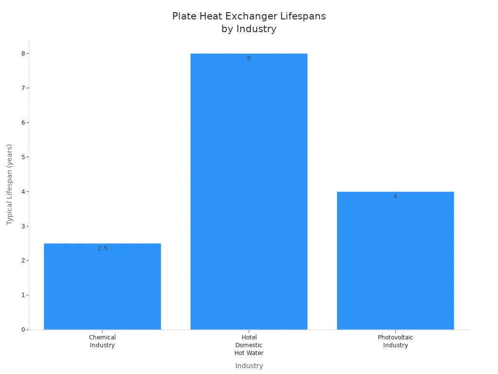
Operational lifespan varies by industry. For example, chemical plants may see 2-3 years of service due to harsh conditions, while hotel hot water systems can exceed eight years with proper materials and care.
Plate heat exchangers deliver exceptional heat transfer efficiency, compact size, and operational flexibility.
They outperform traditional designs by offering up to five times greater efficiency, easy expandability, and straightforward maintenance.
Their modular construction and high turbulence design support energy savings and sustainability goals across industries.
Understanding key components, flow arrangements, and maintenance practices enables engineers to maximize system efficiency and extend equipment lifespan. Plate heat exchangers stand out as a reliable solution for efficient heat transfer in diverse applications.
FAQ
What is the main advantage of plate heat exchangers over shell-and-tube designs?
Plate heat exchangers provide higher thermal efficiency due to their large surface area and turbulent flow. They also offer a compact footprint and easy maintenance, making them ideal for space-limited or high-performance applications.
How often should operators clean a plate heat exchanger?
Operators should inspect and clean plate heat exchangers at least once a year. More frequent cleaning may be necessary in systems with hard water, high fouling risk, or critical temperature control requirements.
Can plate heat exchangers handle high-pressure applications?
Most standard plate heat exchangers operate at moderate pressures. For high-pressure applications, manufacturers offer reinforced frames and thicker plates. Always verify pressure ratings before installation.
What materials are commonly used for plates and gaskets?
Component | Common Materials |
|---|---|
Plates | Stainless steel, titanium |
Gaskets | NBR, EPDM, PTFE |
Material selection depends on fluid type, temperature, and chemical compatibility.