The Ultimate Guide to PTFE Film for Wire and Cable Applications
PTFE film is a thin, non-porous fluoropolymer sheet made from polytetrafluoroethylene, and it stands as the ultimate insulation choice for demanding wire and cable applications. Its low dielectric constant of about 2.1 remains stable across frequencies and temperatures, according to Polyfluoro Ltd. A continuous service rating of 260°C, with brief excursions above 300°C, plus near-total chemical inertness complete the case. This guide helps engineers and buyers make three practical decisions: material selection, specification, and processing of ptfe cable film.
What Is PTFE Film?
Definition and Composition
PTFE film is a thin sheet of polytetrafluoroethylene, a high-performance fluoropolymer built from tetrafluoroethylene. The molecule forms a long chain of repeating [CF2-CF2] units. Versiv Composites explains how this structure produces the film's signature behavior.
| Structural feature | Contribution to properties |
|---|---|
| Carbon backbone | A strong carbon-carbon chain supports a stable outer layer and gives non-stick release performance |
| Fluorine shield | A dense helical sheath of fluorine atoms repels other materials and lowers friction |
| Steric protection | Tight fluorine packing blocks outside molecules from reaching the carbon core, so chemicals and heat struggle to break the polymer down |
| Few mobile charge carriers and low moisture absorption | Excellent dielectric properties and electrical insulation |
| Strong carbon-fluorine bonds | Resistance to ultraviolet radiation and minimal photochemical degradation outdoors |
How PTFE Film Is Manufactured
Skiving is the most common route. A sintered PTFE billet mounts on a rotating mandrel, and a knife blade peels off thin layers from the surface. The blade advances along the block and removes a thin layer with each pass. Bladen PTFE reports that skiving produces flat film with thicknesses as low as 0.001 inches.
Turning works on the same principle with a continuous, ultra-sharp linear blade. PTFE expands roughly ten times more than most metals under heat, so turning heat can shift dimensions and create uneven thickness. Yaxing Flon notes that CNC-controlled skiving holds tolerances of plus or minus 0.01 mm for film under 0.5 mm. Standard PTFE cannot melt extrude, so manufacturers rely on skiving or dispersion calendering.
Forms and Formats for Cable Use
Suppliers convert PTFE into several formats for ptfe cable film duties. Evantic lists unsintered tapes for critical wire and cable, skived sintered film for interwire slip layers, and expanded PTFE for high-frequency coaxial cables. Conductive unsintered tapes serve shielding and grounding, and laser-markable tapes support wire identification.
Key Properties for Wire and Cable
Electrical Performance
Signal integrity depends on how well an insulation material stores and releases electrical energy. PTFE film excels here. Its dielectric constant sits near 2.0 to 2.1, one of the lowest values among solid insulating materials. PCB Tok reports that this value stays stable from direct current up to millimeter-wave frequencies, with testing at 40 GHz showing barely any change. The dissipation factor, or loss tangent, measures roughly 0.0002 to 0.0004. That low loss means very little signal energy converts to heat inside the insulation.
| Property | Value | Frequency note |
|---|---|---|
| Dielectric constant (pure PTFE) | 2.0 to 2.1 | Stable from DC up to millimeter-wave frequencies; tested at 40 GHz with barely any change |
| Dielectric constant (commercial PTFE composites for PCB) | 2.2 to 3.5 | — |
| Dissipation factor (loss tangent) | approximately 0.0002 to 0.0004 | — |
| Frequency stability | Stable dielectric constant | 50-ohm transmission line stays 50 ohms whether running 1 MHz or 10 GHz signals; maintains low dielectric constant at millimeter-wave frequencies (28 GHz and beyond) |
Frequency stability carries real design value. A 50-ohm transmission line built with PTFE film stays at 50 ohms whether it carries a 1 MHz signal or a 10 GHz signal, according to PCB Tok. Engineers can therefore specify one insulation thickness across a product family and trust the impedance to hold. The same source notes that the low dielectric constant persists at 28 GHz and beyond, a range where many materials begin to drift.
Material choice still involves tradeoffs. PTFE does not melt-process, so very thin-wall tubing is difficult to produce from it. FEP fills that gap. Pby Plastics explains that FEP offers high dielectric strength, a low dielectric constant, and minimal moisture absorption, and its melt processability allows the precision and thinness that fine wire insulation demands. FEP suits electronics that do not need an extreme temperature range. PTFE film remains the stronger option when electrical stability must hold across both frequency and temperature extremes.
Thermal Stability
PTFE film serves continuously at 260°C and tolerates brief excursions above 300°C. Those ratings matter in aircraft engines, industrial ovens, and downhole tools, where insulation must survive heat that would degrade PVC or polyethylene in minutes. The material also resists thermal cycling without losing its dimensions. Patsnap's materials database reports that tetrafluoroethylene copolymer films hold expansion and contraction within plus or minus 1 percent in both directions.
| Metric | Value |
|---|---|
| Thermal expansion/contraction rate (tetrafluoroethylene copolymer films) | within ±1% in both directions |
| Thermal expansion coefficient of PTFE-modified polyimide substrate | 40-60 ppm/°C |
| Thermal expansion coefficient of electrodeposited copper foil | 17 ppm/°C |
| Thermal cycling range (substrate/copper foil) | -55°C to +125°C, 500-1000 cycles |
| Dimensional tolerance of PTFE seals through thermal cycling | ±0.05 mm |
| Thermal cycling range (cryogenic seals) | -253°C (liquid hydrogen temperature) to +150°C (engine compartment temperature during operation) |
| Thermal contraction coefficients of metal mating surfaces (aluminum or stainless steel) | 5-10 times lower than untreated PTFE |
The expansion coefficient deserves attention during design. Patsnap lists 40 to 60 ppm/°C for a PTFE-modified polyimide substrate against 17 ppm/°C for electrodeposited copper foil. A wrapped construction therefore moves differently from its conductor as temperature changes. Engineers account for this mismatch through wrap tension, overlap design, and sintering conditions. Modified PTFE grades narrow the gap. Patsnap describes how nanoparticle-induced nucleation of crystalline domains with preferential orientation reduces the anisotropy of thermal expansion coefficients. The nanoparticles also create physical crosslinks through polymer chain adsorption, which restricts segmental mobility and reduces creep under sustained stress. These mechanisms keep wrapped insulation tight through repeated heating and cooling.
Chemical and Environmental Resistance
PTFE film resists attack from nearly every industrial chemical. No known solvent dissolves the polymer at room temperature. Only molten alkali metals and fluorine gas at elevated temperatures react with it, according to Patsnap's chemical resistance data. That inertness protects the conductor from corrosion and keeps the insulation intact in spill, washdown, and immersion scenarios.
| Chemical / Medium | Test Conditions | Result |
|---|---|---|
| Chlorinated solvents (methylene chloride, trichloroethylene, perchloroethylene) | 1-year immersion at 25°C | No swelling (<0.01% volume change) or extraction of oligomers |
| Aromatic hydrocarbons (benzene, toluene, xylene) | 5,000-hour exposure | Contact angle remains >105°, indicating no surface modification |
| Ketones and esters (acetone, MEK, ethyl acetate) | Equivalent thickness | Permeation rates 10-100× lower than nitrile rubber or neoprene |
| Strong oxidizers (hydrogen peroxide 30%, chlorine gas, ozone) | >10,000 hours at 25°C | Stable; limited attack only at >150°C with concentrated oxidizers |
| Concentrated sulfuric acid (98%) | 80°C, 30 days | Weight change <0.05%, tensile strength retention >98%, no visible surface degradation |
| Hydrofluoric acid (48%) | 60°C, 90 days | Zero measurable permeation, dimensional change <0.1% |
| Sodium hydroxide (50%) | 100°C, 60 days | Mechanical properties unchanged, surface contact angle maintained at 110° ±2° |
| Nitric acid (70%) | 25°C, 180 days | No oxidative attack detected by FTIR spectroscopy, crystallinity unchanged per DSC analysis |
| Sulfuric acid (98%) | 200°C, 500 hours | <0.2% weight change and no embrittlement |
| Sulfuric acid (98%) and sodium hydroxide (50%) | 8-hour exposure | Permeation rates below 0.1 μg/cm²/min |
| Solvents (general) | Room temperature | No known solvents dissolve PTFE at room temperature; only molten alkali metals and fluorine gas at elevated temperatures react with the polymer |
Outdoor exposure adds ultraviolet light, moisture, and ozone to the list of threats. Daikin Chemicals rates PTFE at the top grade, A+, for UV resistance, hydrolysis resistance, and ozone resistance. PFA and FEP share that rating. ETFE, EFEP, CPT, and PCTFE sit one step lower at A. The ratings are representative rather than guaranteed, yet the pattern is clear. A ptfe cable film jacket or wrap shrugs off sunlight, humid air, and electrical discharge byproducts that crack rubber and embrittle ordinary plastics. This durability explains the material's long service in outdoor antennas, solar installations, and exposed industrial wiring.
Mechanical and Physical Characteristics
PTFE film combines a low coefficient of friction with moderate abrasion resistance, and that pairing shapes how it performs in cable constructions. The surface feels slippery to the touch. A wrapped ptfe cable film slides against itself and against conductors during taping, so installation runs smoothly and the finished cable resists chafing where it bends or vibrates.
Friction data tell the story clearly. Engineered Materials Inc. reports a coefficient of friction of roughly 0.04 to 0.10 for PTFE under ASTM D1894, one of the lowest values among solid industrial materials. The same source rates PTFE abrasion resistance as moderate, well below the excellent rating it assigns to UHMW polyethylene.
| Property | UHMW | PTFE |
|---|---|---|
| Coefficient of friction (ASTM D1894) | ~0.10-0.22 | ~0.04-0.10 |
| Abrasion resistance | Excellent | Moderate |
That moderate abrasion rating does not disqualify PTFE film from cable duty. Most cable insulation sees sliding contact rather than aggressive scraping. The low friction reduces the cutting and galling that shorten insulation life in tight bundles and connector backshells. Where abrasion loads run high, designers add a protective jacket or choose a filled grade.
Surface condition changes the friction picture. Kintek Solution notes that a rougher mating surface abrades PTFE and raises both friction and wear. Smooth conductors and polished mandrels therefore help the film keep its low-friction advantage through processing and service.
Fillers offer a second lever. Glass, carbon, and bronze additives improve wear resistance and compressive strength. Kintek Solution points out that these fillers always come at the cost of a higher coefficient of friction. A cable engineer who needs better creep resistance under clamp pressure may accept that trade. A engineer who prioritizes signal-cable flexibility may stay with virgin film.
Bulk mechanical values round out the profile. PTFE film shows moderate tensile strength and high elongation at break, so it conforms to conductor contours without cracking. Density sits near 2.1 to 2.2 g/cm³, heavier than polyethylene but predictable for weight budgeting. The film stays flexible at cryogenic temperatures and does not turn brittle in deep cold. Patsnap's data on cryogenic seals shows PTFE functioning from -253°C up to +150°C without loss of dimensional tolerance.
Creep resistance deserves attention during specification. Virgin PTFE flows slowly under sustained load, a behavior that matters at connector interfaces and clamp points. Modified grades with nanoparticle reinforcement restrict chain mobility and reduce creep, as Patsnap describes. Designers who expect long-term compression should request creep data at the expected service temperature and load.
PTFE Cable Film Applications
Cable Types That Use PTFE Film
PTFE film serves as the insulation layer in coaxial cables, RF cables, and other high-frequency transmission lines, according to Cylex Plastics. The material also appears in aircraft wiring, automotive harnesses, and 5G millimeter-wave assemblies. Each cable type draws on the same core strengths: stable impedance, heat tolerance, and low signal loss.
Specific Use Cases
Aerospace systems rely on ptfe cable film for communication and navigation links. GRP reports that the film operates from -200°C to +260°C and tolerates brief exposure above 300°C. The same source notes that its EMI shielding protects sensitive electronics from interference, and its light weight supports aircraft fuel-efficiency goals.
Automotive wiring benefits in similar ways. Modern vehicles pack dense electronics into engine compartments, and electric and hybrid platforms raise heat and chemical exposure. PTFE film insulates these circuits and shields driver-assistance systems from interference, per GRP.
Telecommunications rounds out the picture. Cylex Plastics lists 5G high-frequency applications as a growing demand driver, because millimeter-wave communication needs low-loss materials. Spacecraft electronics also depend on the film to survive extreme temperature swings.
PTFE high-speed cable film plays a substantial role in the aerospace sector thanks to its distinctive properties. Its strong insulation durability and superb heat resistance make it suitable for electrical applications within aircraft systems.
Designers who match film format to these environments gain reliable performance across the cable's service life.
PTFE Film vs. Alternative Materials
Technical Performance Comparison
PTFE film holds the widest thermal window among common cable insulations. Cable Harness Assembly compares PTFE, polyimide, FEP, silicone, and XLPE across key metrics. PTFE and polyimide both reach 260°C continuous service, while FEP and silicone stop at 200°C and XLPE at 125°C. PTFE also reaches -200°C on the cold side. Its dielectric strength earns a top rating, and its chemical resistance matches FEP at the highest level. Flexibility is the tradeoff: PTFE rates lower than FEP and silicone, so tight bend radii need careful design.
| Property | PTFE | Polyimide | FEP | Silicone | XLPE |
|---|---|---|---|---|---|
| Max continuous temp | 260°C | 260°C | 200°C | 200°C | 125°C |
| Min temp | -200°C | -269°C | -200°C | -60°C | -40°C |
| Chemical resistance | Highest | High | Highest | Moderate | Moderate |
| Flexibility | Low | Moderate | High | Highest | High |
| Relative cost | Highest tier | High tier | Mid tier | Low tier | Lowest tier |
Application Fit by Material
Each material fits a distinct duty. Holscot's fluoropolymer selection guide points to PTFE for the highest combined temperature and chemical exposure. FEP and PFA suit high chemical resistance with flexibility, and FEP also serves extrusion and heat-shrink fabrication. ETFE wins on outdoor durability and impact resistance. Greater Wire notes that PTFE serves aerospace, RF, and military cables, while FEP covers data and medical wires and ETFE handles automotive and photovoltaic work. XLPE remains the economical choice for power distribution at moderate temperatures.
Regulatory Compliance
Flame resistance shapes code compliance for cable insulation. Greater Wire rates PTFE flame resistance as outstanding, with FEP and PFA close behind. Plenum and transit codes often demand low smoke and low flame spread, and fluoropolymer films meet those requirements more easily than polyethylene. Buyers should request the specific flammability test reports for their target market before finalizing a specification.
Cost Considerations
PTFE film carries the highest purchase price among common cable insulations, as the earlier comparison table shows. Buyers should weigh that premium against total cost of ownership rather than unit price alone. Patsnap's cost analysis reports that a five-year view typically shows a positive return on investment, with maintenance costs reduced by 30 to 50 percent compared with non-PTFE alternatives. Several factors drive those savings:
- Reduced downtime, lower replacement part costs, and decreased energy consumption from improved efficiency
- A 40 percent reduction in maintenance-related downtime reported by some companies after adopting PTFE-based equipment
- Longer component life through improved coating techniques, composite formulations, and surface treatments that cut replacement frequency
Recycling and reprocessing methods also help lower long-term PTFE costs by reducing waste and extending product life, according to Patsnap. The same source notes that PTFE production involves energy input and waste-management challenges, and the material's longevity offsets part of that burden by reducing replacement frequency.
Grade selection protects the budget. Astau reports that PFA typically costs 30 to 50 percent more than PTFE for the same component. Over-specifying PFA where PTFE meets the technical requirements adds expense with no gain. Under-specifying PTFE in a PFA-grade application usually leads to premature failure and costlier rework.
| Application | Benefit | Cost consideration | Mitigation |
|---|---|---|---|
| Chemical processing | Resistance to corrosive chemicals and solvents | Higher initial material costs | Evaluate long-term cost benefits |
| Electrical insulation | Thermal stability and electrical insulating properties | High processing temperatures required | Select processing conditions carefully |
| Automotive | Durability and non-stick properties | Potential wear over time | Schedule regular maintenance |
Cy-PTFE summarizes the balance well: PTFE hydrophobic films extend product lifespan and reduce maintenance costs, yet cost and environmental impact remain significant considerations for widespread adoption.
Selection and Specification Guide
Defining Your Requirements
A successful ptfe cable film specification starts with a clear picture of the cable's job. Engineers should write down the operating environment before they compare any product data sheet. Three requirement families drive every later decision: electrical, thermal, and mechanical.
Electrical requirements begin with impedance and signal frequency. A 50-ohm coaxial design needs a dielectric constant near 2.1 to hold its target impedance. High-frequency links push the requirement further. Millimeter-wave assemblies demand a stable dielectric constant and a low dissipation factor at 28 GHz and beyond. The required dielectric strength follows from the voltage stress the insulation will see. CGS Tape reports that PTFE film insulates up to 500 volts per mil, a figure that guides wall-thickness planning for medium-voltage builds.
Thermal requirements set the continuous service temperature and the excursion profile. A downhole tool or an engine-bay harness may need 260°C continuous service with brief spikes above 300°C. A medical data cable may never exceed 150°C. The cold end matters too. Cryogenic service near -200°C rules out many polymers and favors fluoropolymers. Engineers should also record the number of thermal cycles the cable will face. Repeated heating and cooling stresses the wrap-to-conductor interface, and the design must tolerate that movement.
Mechanical requirements cover bend radius, abrasion exposure, and clamp pressure. Tight routing in an aircraft bundle demands flexibility and a small minimum bend radius. A fixed industrial run tolerates a stiffer construction. Connector backshells and clamps apply sustained compression, so creep resistance enters the requirement list. The engineer should note any flexing duty, because dynamic flexing loads the film far more than a static install.
A written requirements table keeps the team aligned. Each row states a parameter, a target value, and a test method. This table becomes the reference for every supplier conversation and every incoming inspection.
Key Specifications to Request
Suppliers quote PTFE film against a standard set of properties. Buyers should request each value in writing and confirm the test method behind it. CGS Tape publishes a representative product table that shows how format and thickness shift the numbers.
| Product Number | Film Type | Density (g/cm³) | Tensile Strength (psi) | Elongation (%) | Dielectric Strength (V/mil) |
|---|---|---|---|---|---|
| CGS-1258 (1 mil) | 1 Mil Skived | 2.13–2.19 | 3000 | 200 | 3000 |
| CGS-1258 (2 mil) | 2 Mil Skived | 2.13–2.19 | 3000 | 200 | 3000 |
| CGS-1258 (3 mil) | 3 Mil Skived | 2.13–2.19 | 3000 | 200 | 3000 |
| CGS-1258 (5 mil) | 5 Mil Skived | 2.13–2.19 | 3500 | 300 | 2000 |
| CGS-1358 (3 mil) | 3 Mil Unsintered | 1.50–1.70 | 1800 | 50 | 2500 |
The table carries a clear lesson. Skived film holds a density near 2.15 g/cm³ and a dielectric strength of 3000 V/mil at thin gauges. The 5 mil skived grade trades some dielectric strength for higher tensile strength and elongation. Unsintered film shows lower density, lower tensile strength, and much lower elongation. CGS Tape notes that both skived and unsintered film meet the strict requirements of modern cable construction. The chart below, from CGS Tape, compares these five film types across the same four properties.
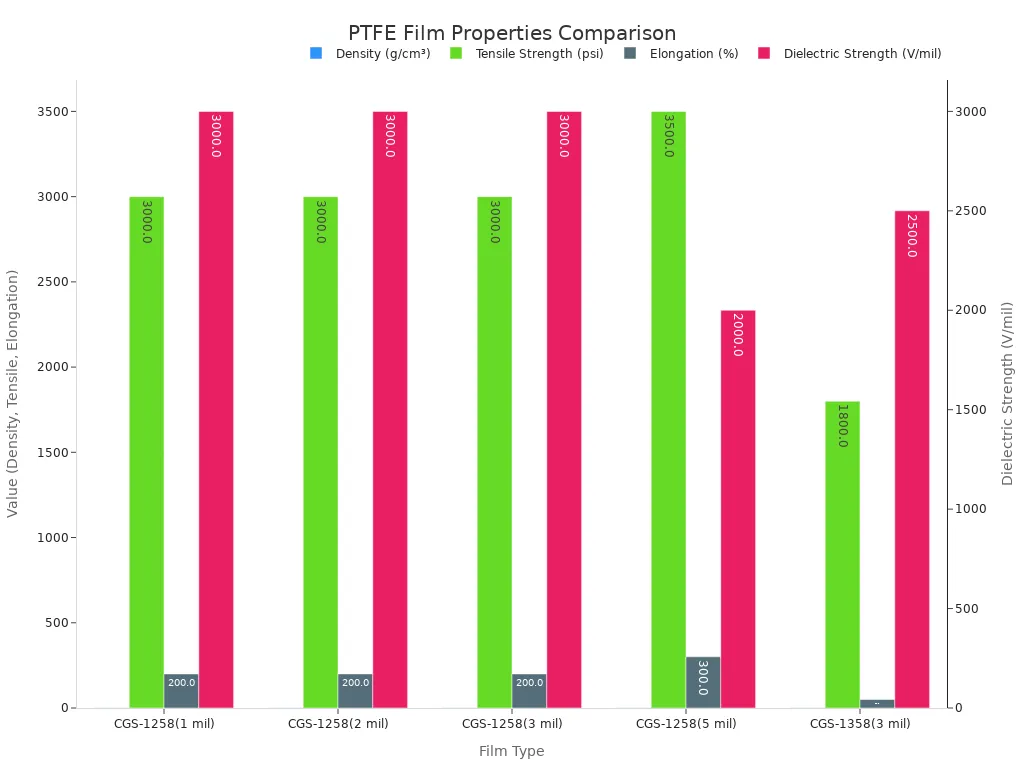
A specification sheet should list more than the headline numbers. Buyers should ask for dielectric constant and dissipation factor at the service frequency. They should request thermal expansion data, because the film moves differently from copper as temperature changes. Chemical resistance data belongs on the list for exposed routes. Flammability test reports matter for plenum and transit installations. Druflon adds a further point: corona-resistant PTFE grades offer roughly a thousand-fold longer high-voltage life than pure PTFE, with strong resistance to electro-mechanical and chemical-mechanical stress cracking. Druflon also notes that PTFE stays free of embrittlement at very high and very low temperatures. High-voltage designs should therefore request the corona-resistant grade by name.
Tolerance belongs on the request list as well. Thickness tolerance drives impedance consistency in coaxial builds. Width tolerance affects wrap coverage and overlap control. Buyers should state the acceptable range and ask the supplier to confirm capability against it.
Matching Film Format to Process
The film format must fit the cable-making process. A mismatch here causes scrap, rework, and field failures. Three formats dominate cable work: skived sintered film, unsintered tape, and expanded PTFE.
Skived sintered film suits wrapping and taping operations that need a dense, void-free layer. The film arrives fully sintered, so the cable maker skips a heat cycle. It holds its dimensions through the wrap and resists compression at clamps. Designers choose skived film for interwire slip layers and for insulation builds where density and dielectric strength matter most.
Unsintered tape behaves differently. It feels softer and conforms tightly to conductor contours. The cable maker wraps the tape and then sinters it in place. Sintering fuses the wrap layers into a homogeneous wall. This route suits critical wire and cable constructions that need a seamless insulation layer. The process adds a furnace step, so the production line needs the right oven capacity and temperature control. Unsintered tape also supports conductive and laser-markable variants for shielding and identification duties.
Expanded PTFE serves high-frequency coaxial cables. The expansion process introduces air into the film, and air lowers the effective dielectric constant. A lower dielectric constant raises signal velocity and cuts loss. Cable designers pick expanded PTFE when low loss at high frequency outweighs the mechanical strength of solid film.
Process matching extends to the wrapping method. A helical wrap with overlap needs a film width and thickness that match the taping head. A longitudinal wrap needs different tension control. Buyers should share their taping equipment details with the film supplier. The supplier can then recommend a format, a thickness, and a roll length that fit the line. A trial run on production equipment confirms the match before the team commits to a purchase order.
Installation and Processing Considerations
Wrapping and Taping Methods
Consistent tension and controlled overlap determine wrap quality. Cableteque recommends starting and ending wraps without sharp edges, and tapering the ends when a heat-shrink follows. Bulky steps at start and finish points create stress risers for clamps. Assemblers should follow a few proven practices:
- Use multiple layers where thermal or abrasion risk runs highest, and secure the end with a compatible adhesive patch or a terminating heat-shrink boot.
- Avoid adhesives that migrate under heat or oils.
- Use PTFE-impregnated glass braid at backshells and clamp points, and document the braid as a separate part number on the BOM.
- Add visual checks for lifted edges, exposed conductors, and uniform overlap to traveler documents.
Cableteque publishes common tape parameters for reference:
| Parameter | Specification |
|---|---|
| Widths | 3/8 inch, 1/2 inch, 3/4 inch |
| Overlap | 30 percent to 50 percent |
| Layers | 1 to 3 |
| Adhesive | Silicone PSA for high heat, acrylic PSA for general use |
| Documentation | Datasheet, lot traceability, outgassing data |
Sintering and Heat Treatment
Unsintered ptfe cable film fuses into a homogeneous wall during sintering. The furnace profile must match the tape thickness and the conductor mass. A slow ramp prevents trapped volatiles from blistering the wrap. Controlled cooling protects the insulation from stress cracking. Cable makers should confirm oven capacity and temperature uniformity before committing a design to unsintered tape.
Handling and Storage Best Practices
PTFE film demands careful storage. HCP and Micflon both recommend a cool, dry environment with stable temperatures between 15°C and 25°C and relative humidity below 60 percent. Film stays flat on a smooth, level surface, and interleaving paper prevents layer adhesion. Opaque packaging blocks UV light, which can embrittle the surface. Clean, dry gloves prevent oil transfer, and first-in, first-out rotation keeps older stock moving.
PTFE film earns its place in demanding wire and cable work through a rare combination: a stable dielectric constant near 2.1, continuous service at 260°C, and near-total chemical inertness. The selection framework stays simple. Engineers match film format and specification to electrical, thermal, and mechanical requirements, then confirm the choice with test data. DuPont continues to advance PTFE formulations, adding nano-fillers that boost mechanical strength and abrasion resistance while preserving electrical performance. Market trends point toward higher-frequency signal demands and thinner, higher-performance insulation. Patsnap reports several developments shaping the future of ptfe cable film:
- Growing demand for high-speed data transmission drives adoption of advanced insulation materials like PTFE.
- Ultra-thin PTFE coatings and foam-based insulations reduce the material required for effective insulation.
- Hybrid insulations combining PTFE with carbon nanotubes and graphene promise enhanced properties for 5G communications, electric vehicles, and advanced robotics.
FAQ
What makes PTFE film suitable for wire and cable insulation?
PTFE film offers a dielectric constant near 2.1, continuous service at 260°C, and near-total chemical inertness. These properties hold stable across frequency and temperature extremes. Engineers therefore specify the film for coaxial, aerospace, and high-frequency cables that demand reliable signal integrity and long service life.
Does PTFE film work at both high and low temperatures?
PTFE film serves continuously at 260°C and tolerates brief excursions above 300°C. The material also remains flexible near -200°C without turning brittle. This wide window covers engine bays, downhole tools, and cryogenic equipment. Few insulation materials match this combined thermal range.
Which film format suits a given cable design?
Skived sintered film fits wrapping operations that need a dense, void-free layer. Unsintered tape conforms tightly to conductors and fuses during sintering. Expanded PTFE lowers the effective dielectric constant for low-loss coaxial cables. Designers match the format to their taping equipment and electrical targets.
Does every PTFE film application require sintering?
Only unsintered tape needs a sintering step. The cable maker wraps the tape and heats it to fuse the layers into a homogeneous wall. Skived sintered film arrives fully processed, so the production line skips the furnace cycle entirely.
How does a buyer justify the higher cost of PTFE film?
PTFE film carries the highest purchase price among common insulations. A five-year view typically shows positive return on investment, with maintenance costs reduced by 30 to 50 percent. Longer component life and less downtime offset the initial premium.
See Also
Best Precoat Materials for Filtration Systems in 2025
Key WT20 Thoriated Tungsten Electrode Facts for Better TIG Welding
Steel Processing for Heat Exchange Applications Consistently Delivers Strong Results
A Beginner’s Guide to Choosing the Right Power Transformer
2025 Guide to Semi-Welded Plate Heat Exchangers for Industrial Use