Prevent UV Print Misalignment by Setting X and Y Values Correctly
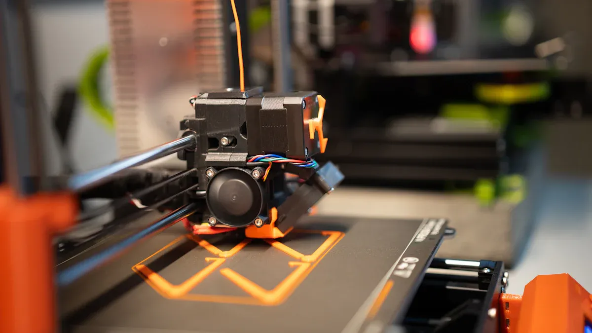
I often see UV PRINTER misalignment. While many factors cause this, such as non-vertical nozzles or incorrect print height, my solution is setting the X/Y coordinates correctly. I home the print head for the origin, measure to the object, and then input the values. This method works perfectly on the 3250 A3 UV PRINTER, 4030Pro A3 UV Flatbed Printer, 4050 A2 UV Flatbed Printer, 4060Plus A2 UV Flatbed Printer, and 6090Pro A1 UV Flatbed Printer. Learn how to set the desired print position; feel free to communicate with us if you need help.
Key Takeaways
- Always find your printer's home position first. This is the true starting point for all your measurements.
- Measure the distance from the home point to your object's top-left corner. Enter these X and Y numbers into your printing software.
- Always do a test print on scrap material. This step helps you check if your print is in the right spot before you print on your final item.
The Fundamental 4-Step Process for Manual Alignment
I have refined my workflow into a straightforward, four-step process. Following these steps consistently eliminates guesswork and prevents costly printing errors. This method gives me precise control over where my design lands on the object, every single time.
Step 1: Find and Mark the Origin Point
First, I establish the printer's absolute starting point. I do this by using the control panel on my UV PRINTER to send the print head to its "home" position. This action moves the carriage to the machine's fixed zero point.
Technically, I define this origin point as the intersection of the X, Y, and Z axes, where X=0 and Y=0. This point serves as the prime reference from which I calculate all other positions. Finding this home position is the foundation of accurate manual alignment because it synchronizes my design file, the machine's setup, and the material's placement on the bed.
Pro Tip: Once the print head is at its home position (0,0), I use a non-permanent marker to place a small dot on the print bed directly under the center of the UV lamp. This physical mark gives me a constant, visible reference point for all future jobs.
Step 2: Position the Object and Measure Coordinates
With the origin marked, I place my object on the print bed. I position it exactly where I want the final print to appear.
Next, I take a steel ruler and measure the distance from my marked origin point to the top-left corner of the object. I measure the horizontal distance for the X-value and the vertical distance for the Y-value. Accuracy here is critical. I always make sure my eye is directly above the measurement mark on the ruler. Looking from an angle can cause parallax error, where the measurement appears to shift, leading to an incorrect reading.
How I Avoid Parallax Error:
- I align my eye directly in line with the measurement scale.
- I ensure my line of sight is perpendicular to the ruler.
- I maintain a consistent viewing distance during the measurement.
Step 3: Enter Coordinates into RIP Software
Now I move from the hardware to the software. I open my design in the RIP (Raster Image Processing) software. In my experience, I've worked with several common RIPs, and the process is similar across them:
- Onyx Graphics
- Wasatch SoftRIP
- SAi Flexi
- Caldera
In the software's layout or position settings, I find the input fields for the X and Y coordinates. I carefully enter the X and Y values that I just measured. It is crucial to double-check that the measurement units in the software (e.g., millimeters or inches) match the units on my ruler. A mismatch here is a common source of major alignment problems. While some high-end machines use cameras for automated alignment, I find this manual intervention is essential for guaranteeing precision on unique substrates or complex jobs.
Step 4: Perform a Test Print to Verify
I never commit to a final print without a quick test. This final check saves me from wasting expensive materials and time. Even minor misalignment can have significant financial impacts, especially on jobs like custom-printed items where a small error can lead to a rejected batch. Wasting a piece of scrap material is always cheaper than reprinting an entire order.
My test print process is simple:
- I place a piece of scrap material or paper at the measured coordinates.
- In the RIP software, I create a simple box outline that matches the dimensions of my design or just print the corner marks.
- I run the print job.
If the printed outline lands exactly where it should on the scrap material, I am ready for the final print. If it's misaligned, I know the printer might not be saving calibration values correctly or there's a minor measurement error. I then re-measure and adjust the X/Y values in the software before running another quick test. This systematic check on my UV PRINTER ensures a perfect result.
学会如何定位设置想要打印的位置,如果有更多不了解的可以随时与我们交流
Setting Coordinates on Your UV PRINTER Bed
The physical surface of the print bed directly impacts my alignment strategy. I adapt my approach based on whether the bed has built-in grid lines. Both scenarios require precision, but the methods differ slightly.
For Print Beds Without Grid Lines
A blank print bed offers a clean slate, but it requires me to create my own reference points. My most reliable technique is to print a faint outline of my product directly onto the platform. I then place the physical item perfectly within this printed boundary. For bulk orders, I design and use custom pallets to hold multiple items, ensuring consistent alignment after the initial setup.
I strongly advise against using masking tape for marking positions. In my experience, it leaves sticky residue on the print and can even imprint a tape pattern on the final product. It also wears out after just a few uses. While some operators use it, I find a light-duty glue stick or simply printing a guide offers far better and cleaner results for my UV PRINTER.
For Print Beds With Grid Lines
When my printer bed has built-in grid lines, the process becomes much faster and more repeatable. These lines create a numbered coordinate system right on the bed. 🗺️
I simply place my object on the bed and note the line numbers where its top-left corner aligns. For example, I might place an item to start at column line 2 and row line 3. This gives me exact coordinates for repeatable jobs without needing a ruler for every print. For larger items, I can note the start line and then see how many grid tracks the object spans. This method allows me to position items with absolute confidence, eliminating guesswork and ensuring perfect placement every time.
学会如何定位设置想要打印的位置,如果有更多不了解的可以随时与我们交流
I consistently achieve perfect alignment by following these core principles. I always establish the origin, measure coordinates precisely, and confirm my software units match my ruler. A quick test print is my non-negotiable final check. While advanced tools like laser guides offer automation, mastering this manual process for my UV PRINTER provides absolute control and prevents costly errors. 🎯
FAQ
What if my print is still slightly off after measuring?
I re-measure carefully, checking for parallax error. Then, I make small, incremental adjustments to the X/Y values in my RIP software and run another quick test print. Precision is key.
Why can't I just use the corner of the print bed as my origin?
💡 The machine's electronic home position is its true (0,0) reference. Using the physical corner introduces guesswork. I always home the print head to guarantee a consistent, accurate starting point.
学会如何定位设置想要打印的位置,如果有更多不了解的可以随时与我们交流
See Also
Automatic UV Coaters: Indispensable for Modern High-Speed Printing Operations
Versatile Nozzle Technologies: Catering to Gardening, Bioprinting, and Lubrication Needs
Next-Gen Folder Gluer Innovations Shaping 2025 Carton Production Lines
Top 8 HTN LCD Displays Delivering Peak Performance and Dependability
Exploring Micro-Channel Technology for Hydrogen Fuel Cell Heat Exchanger Efficiency