Optimizing Signal Integrity: The Engineering Behind High-Performance Coaxial Design
High-performance coaxial design hinges on meticulously controlling a cable's physical geometry and material properties to manage characteristic impedance. This process involves the precise engineering of conductors, dielectrics, and shielding.
The primary goals are to minimize signal attenuation, prevent reflections, and shield the coaxial cable from interference. This ensures unwavering signal fidelity, especially at high frequencies.
The Foundation of Signal Integrity: Characteristic Impedance
Characteristic impedance is the single most important electrical property of a coaxial cable. It is not a simple measure of resistance; instead, it represents the relationship between voltage and current for a traveling electromagnetic wave. Engineers design every aspect of a high-performance cable to achieve and maintain a specific impedance value. This control is essential for preventing signal reflections and maximizing power transfer from the source to the load.
The Impedance Formula: Conductor Diameter Ratios
The characteristic impedance (Z₀) of a cable is determined by its physical dimensions and the material separating its conductors. The relationship is defined by a precise mathematical formula.
Z₀ = (60/√εr) × ln(D/d)
In this equation, D is the inner diameter of the outer conductor (the shield), and d is the outer diameter of the center conductor. The natural logarithm of the ratio D/d is a primary factor in the calculation. This means that precise manufacturing control over these two diameters is critical for producing a cable with a consistent impedance along its entire length. This formula allows engineers to design cables for specific industry-standard impedances.
- 50 Ohms: This impedance is the standard for high-power RF applications. It is used in radio transmitter antenna connections, test and measurement equipment, and data communications like Ethernet.
- 75 Ohms: This impedance is optimized for video and audio. It is the standard for television signals, video distribution systems, and digital audio connections.
The Role of the Dielectric Constant (εr)
The second critical variable in the impedance formula is εr, or the relative dielectric constant. This value represents the insulating material's ability to store electrical energy in an electric field. A lower dielectric constant allows an electromagnetic wave to travel faster through the cable, which improves the Velocity of Propagation (VoP). Materials with lower dielectric constants also exhibit less signal loss, or attenuation, making them ideal for high-frequency and long-distance applications.
The choice of dielectric material, therefore, directly influences both impedance and overall performance. Engineers select from a range of advanced polymers to meet specific design goals.
| Material | Typical Dielectric Constant (εr) |
|---|---|
| Solid Polyethylene (PE) | ≈ 2.25 |
| Foamed Polyethylene (FPE) | ≈ 1.5 - 1.8 |
| Solid PTFE | ≈ 2.1 |
| Foamed FEP | ≈ 1.3 - 1.5 |
Note: The dielectric constant can vary slightly depending on the material's specific formulation and the signal's frequency.
Consequences of Impedance Mismatch: VSWR and Return Loss
An impedance mismatch occurs when a cable is connected to a device (like an antenna or amplifier) with a different impedance. This discontinuity causes a portion of the signal's energy to reflect back toward the source instead of being transmitted to the load. These reflections create destructive interference, degrade signal quality, and can even damage transmitter components.
Engineers use two key metrics to quantify the effects of impedance mismatch:
- Voltage Standing Wave Ratio (VSWR): This ratio measures the standing wave pattern created by the combination of the forward and reflected signals. A perfect match has a VSWR of 1:1. Higher values indicate a greater mismatch and poorer power transfer.
- Return Loss: This metric measures the power of the reflected signal relative to the forward signal, expressed in decibels (dB). A high Return Loss value is desirable, as it indicates that very little power is being reflected.
The relationship between these values is direct and inverse. As Return Loss increases, VSWR decreases, signifying a better impedance match and improved system performance.
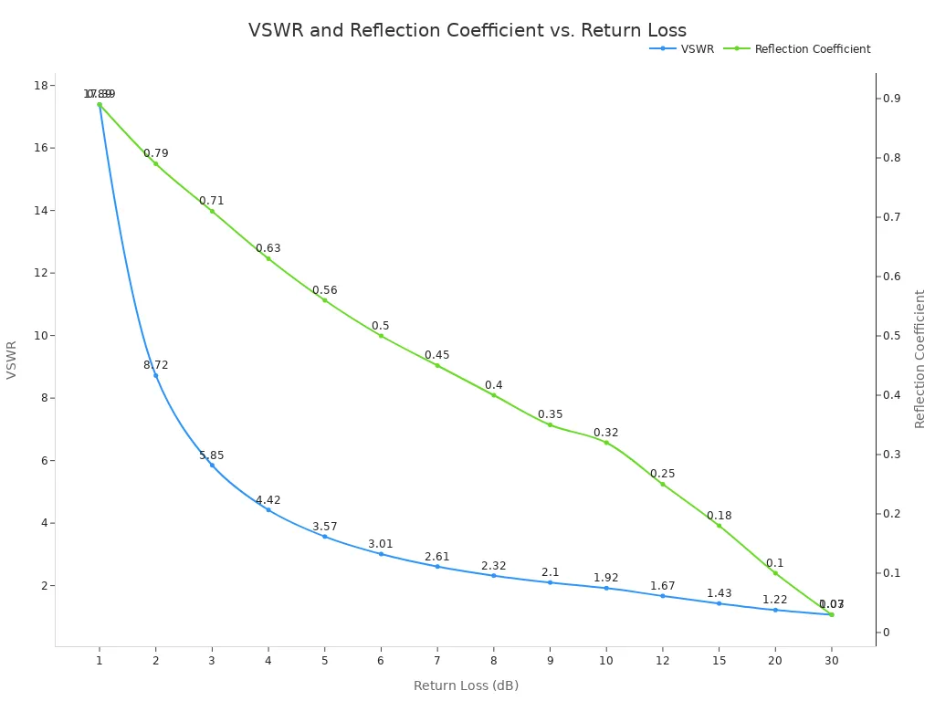
For high-performance systems like 5G infrastructure, a Return Loss greater than 15.56 dB is often considered the minimum acceptable value. This corresponds to a VSWR of approximately 1.4:1, ensuring that over 97% of the power is successfully transmitted to the load.
Combating Signal Loss: The Mechanics of Attenuation
Beyond maintaining impedance, the second great challenge in high-performance cable design is minimizing attenuation. Attenuation is the gradual loss of signal strength as it travels down the length of a cable. This loss, measured in decibels (dB), is unavoidable but can be managed through careful engineering. If left unchecked, a weak signal at the end of the line can lead to poor data rates, dropped calls, or a noisy video feed. Attenuation stems from two primary sources: resistive losses in the conductors and dielectric losses in the insulating material.
Resistive Losses and the Skin Effect
Any electrical current flowing through a conductor with resistance generates heat, dissipating a small amount of energy. This is known as resistive loss. At low frequencies, this loss is relatively minor. However, as signal frequency increases, a phenomenon called the skin effect dramatically increases the effective resistance of the conductors.
The skin effect causes alternating current to concentrate near the surface, or "skin," of a conductor. This phenomenon becomes more pronounced at higher frequencies, reducing the effective cross-sectional area available for current flow. With less area for the current to travel, the conductor's resistance rises, leading to greater resistive losses that escalate proportionally to the square root of the frequency.
The depth to which the current penetrates, known as the skin depth, shrinks rapidly as frequency climbs. For a copper conductor, the effect is stark.
| Material | 1 GHz (µm) | 10 GHz (µm) | 100 GHz (µm) |
|---|---|---|---|
| Copper | 2.07 | 0.654 | 0.207 |
At 10 GHz, the signal travels in a layer of copper less than one micron thick—thinner than a particle of smoke. This makes the surface quality and material of the conductor paramount for high-frequency performance.
Dielectric Absorption and Loss Tangent
Conductors are not the only source of signal loss. The dielectric material separating the inner and outer conductors also absorbs a small amount of electromagnetic energy, converting it into heat. This is called dielectric loss. This type of loss becomes increasingly significant relative to resistive loss as frequencies enter the gigahertz range.
Engineers quantify a material's propensity for this type of loss using a value called the Loss Tangent (tan δ), also known as the Dissipation Factor.
The loss tangent is a dimensionless quantity that measures the inherent dissipation of electromagnetic energy within a material. It is mathematically defined as the ratio of the lossy part of the material's electrical property to the lossless part. A low loss tangent indicates a "fast" substrate with minimal signal loss, while a high value indicates a "slow" substrate.
The choice of dielectric material, therefore, has a direct impact on a cable's high-frequency attenuation. Materials like solid Polytetrafluoroethylene (PTFE) are prized for their exceptionally low loss tangents compared to more common materials like Polyethylene (PE).
| Material | Loss Tangent Value | Frequency |
|---|---|---|
| Solid PTFE (Teflon®) | 0.00028 | 3 GHz |
| Polyethylene LDPE/HDPE | 0.00031 | 3 GHz |
Furthermore, introducing air into the dielectric by foaming the polymer (e.g., creating foamed PE) lowers its effective dielectric constant and its loss tangent, significantly reducing dielectric losses. In some designs, dielectric losses in a solid polyethylene cable can account for 30% of total attenuation, a figure that drops to less than 10% for a foamed polyethylene equivalent.
Engineering Strategies for Low Attenuation
Engineers combat attenuation by making deliberate choices in materials and geometry. Several key factors influence a cable's final attenuation rating:
- Frequency: Attenuation always increases with frequency.
- Conductor Size: Larger conductors have lower resistance and thus lower loss.
- Dielectric Material: Low-loss dielectrics like PTFE or foamed polymers reduce high-frequency loss.
- Cable Length: Loss is cumulative; doubling the cable length doubles the total attenuation in dB.
The following chart compares the attenuation of several common coaxial cable types. It clearly shows that for any given cable, loss increases with frequency. It also illustrates that cables with larger diameters, like RG-11, generally exhibit lower loss than smaller cables like RG-174.
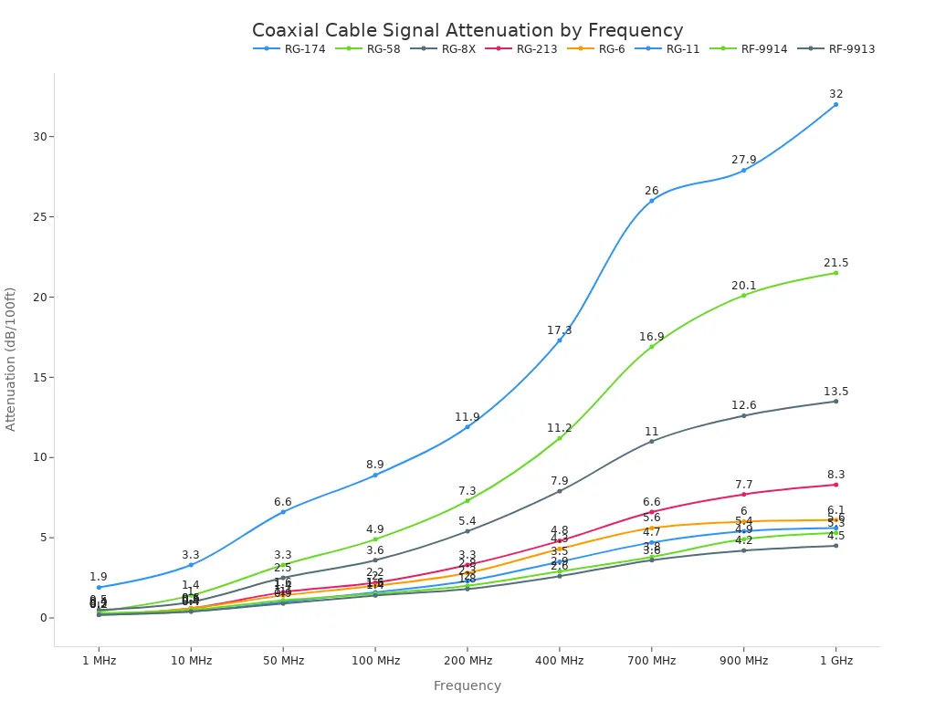
| Coax Cable Type | 1 MHz (dB/100ft) | 10 MHz (dB/100ft) | 100 MHz (dB/100ft) | 1 GHz (dB/100ft) |
|---|---|---|---|---|
| RG-174 | 1.9 | 3.3 | 8.9 | 32.0 |
| RG-58 | 0.4 | 1.4 | 4.9 | 21.5 |
| RG-213 | 0.2 | 0.6 | 2.2 | 8.3 |
| RG-11 | 0.2 | 0.4 | 1.6 | 5.6 |
| RF-9913 | 0.2 | 0.4 | 1.4 | 4.5 |
Note: Attenuation values are per 100 feet. Loss scales linearly with cable length.
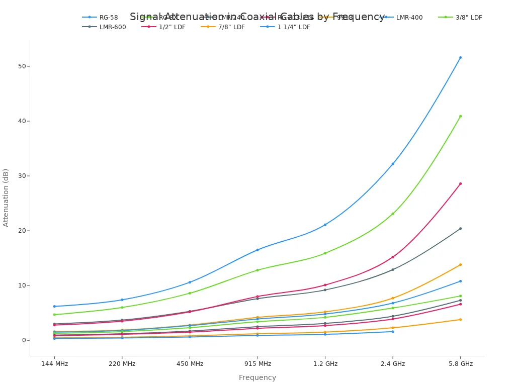
For demanding applications like cellular backhaul or radar systems, engineers turn to specialized low-loss designs. The chart below compares standard cables with high-performance Low-Loss Dielectric Foam (LDF) cables, where the performance benefits of superior materials and larger diameters become obvious. A 7/8" LDF cable, for instance, has an attenuation of only 2.3 dB over 100 feet at 2.4 GHz, whereas a standard RG-58 cable loses over 32 dB over the same distance.
To achieve this level of performance, engineers employ several key strategies:
- Using Premium Low-Loss Dielectrics: They select materials like PTFE or create advanced foam dielectric structures. These materials have extremely low loss tangents and their hydrophobic properties prevent moisture absorption, which can increase loss.
- Specifying High-Purity and Plated Conductors: They use high-purity copper for the center conductor. For superior performance, they specify silver-plated copper, as silver's higher conductivity further reduces skin-effect losses at high frequencies.
- Optimizing Conductor Geometry: They design cables with larger-diameter conductors to lower DC resistance. In some high-frequency designs, the center conductor is made tubular, saving weight and cost without compromising RF performance, since the interior carries almost no current due to the skin effect.
Through this multi-faceted approach, engineers can design a coaxial cable that delivers a clean, strong signal to its destination, even across long distances and at microwave frequencies.
Shielding a Coaxial Cable Against Noise
A coaxial cable must protect its signal from external electromagnetic interference (EMI) and radio frequency interference (RFI). This unwanted noise can corrupt the data or video signal being transmitted. Engineers design shields to act as a barrier against this interference.
Interference sources are everywhere in the modern environment. They can originate from regulated radio transmitters, license-free devices like walkie-talkies, and a wide range of unintentional noise sources.
- Computer equipment and microprocessors
- Motors and lighting fixtures
- Electrical power distribution systems
- Nearby wireless devices
Braid Shielding for Low-Frequency Interference
Braid shielding consists of a mesh of woven metal strands, typically tinned copper or aluminum. This design offers excellent flexibility and physical strength, making the cable durable. The braid is highly effective at blocking low-frequency interference. However, the small gaps in the weave mean it does not provide 100% coverage, which can allow high-frequency signals to penetrate the shield.
Foil Shielding for High-Frequency RFI
Foil shielding uses a thin layer of aluminum, often bonded to a polyester backing for strength. This type of shield provides 100% coverage of the dielectric core. The complete surface area makes foil extremely effective at reflecting high-frequency RFI. While excellent for high frequencies, a simple foil shield can be more fragile than a braid and offers less effective shielding at very low frequencies.
Combination Shields for Broadband Effectiveness
For the best performance, engineers often use combination shields that integrate both foil and braid layers. This design leverages the strengths of both types to achieve superior broadband shielding. The foil layer provides 100% coverage to block high-frequency energy leaks, while the outer braid adds physical strength and protects against low-frequency interference. This dual-layer approach is the optimal choice for high-frequency applications above 100 MHz, ensuring maximum signal protection.
Material Science in Coaxial Design
The performance of a coaxial cable is fundamentally tied to the materials used in its construction. Engineers carefully select specific metals, polymers, and compounds for the conductor, dielectric, and jacket to meet demanding electrical and environmental requirements. Each material choice represents a calculated trade-off between performance, durability, and cost.
Conductor Materials: Copper vs. Silver-Plated Copper
The center conductor's material directly impacts signal loss. Pure copper is the industry standard, prized for its excellent conductivity. While lower-cost alternatives like copper-clad steel exist, high-performance designs require maximum signal transfer. For high-frequency applications, engineers often specify silver-plated copper conductors. Silver has slightly higher conductivity than copper, which helps mitigate skin effect losses. This plating ensures the signal, which travels on the conductor's surface, encounters the least possible resistance.
Dielectric Materials: PTFE, FEP, and Foamed PE
The dielectric insulator is critical for controlling impedance and minimizing signal loss. Engineers choose from several advanced polymers.
- PTFE and FEP: These fluoropolymers are staples in high-performance designs. They offer exceptionally low dielectric constants (≈2.1) and operate across wide temperature ranges.
- Foamed PE: Foaming polyethylene introduces air into the material. This technique lowers the dielectric constant even further, which reduces attenuation and allows the signal to travel faster.
| Material | Max. Temperature | Min. Temperature | Dielectric Constant |
|---|---|---|---|
| PTFE | 260°C (500°F) | -200°C (-328°F) | ~2.1 |
| FEP | 200°C (392°F) | -200°C (-328°F) | ~2.1 |
Jacket Compounds for Mechanical and Environmental Protection
The outer jacket shields the cable's internal components from physical damage, moisture, chemicals, and UV radiation. The choice of jacket material depends entirely on the installation environment.
PVC (Polyvinyl Chloride): An affordable, flexible option for general-purpose use. However, standard PVC can become brittle in cold temperatures and degrades under direct sun exposure without UV inhibitors.
PE (Polyethylene): Offers excellent moisture and UV resistance, making it ideal for outdoor applications. It is typically more rigid than PVC.
FEP (Fluorinated Ethylene Propylene): A premium fluoropolymer jacket that provides superior resistance to extreme temperatures, chemicals, and oils. Its durability and resilience make it the top choice for harsh industrial or aerospace environments.
Advanced Design Considerations for High-Performance Systems
Engineers must account for several advanced factors beyond impedance and attenuation to guarantee peak performance. In systems like phased-array radar and 5G communications, metrics such as phase stability and passive intermodulation become just as critical as signal loss.
Phase Stability and Velocity of Propagation (VoP)
The Velocity of Propagation (VoP) measures how fast a signal travels through a cable relative to the speed of light in a vacuum. This speed is determined by the dielectric material. The relationship is defined by the formula VoP = 1 / √εr, where εr is the dielectric constant. Materials with a lower dielectric constant, like foamed polyethylene, allow signals to travel faster.
Phase stability refers to a cable's ability to maintain a consistent signal phase when it is bent, flexed, or exposed to temperature changes. Engineers measure this by wrapping a cable around a mandrel and recording phase changes across a frequency sweep. For demanding applications, the acceptable phase shift is extremely small.
| Frequency Range | Typical Phase Stability (degrees) |
|---|---|
| Up to 8 GHz | +/- 4.0º |
| 8.01 to 18 GHz | +/- 6.0º |
Minimizing Passive Intermodulation (PIM)
Passive Intermodulation (PIM) is a form of interference generated when two or more strong signals mix at a nonlinear junction in the signal path. This creates unwanted frequencies that can disrupt communication. Common causes of PIM include:
- Loose or dirty connectors
- Contact between dissimilar metals
- Corrosion on conductors or nearby structures (the "rusty bolt effect")
- Damaged cable components
Engineers minimize PIM by making careful design and material choices. They specify high-quality, low-PIM components and use solid conductors with non-oxidizing plating, such as silver. Proper installation, including applying correct connector torque, is also essential to prevent PIM generation.
Manufacturing Tolerances and Consistency
High-performance systems demand absolute consistency from one cable to the next. Manufacturers achieve this through rigorous process control. They implement stringent quality checks on all raw materials to ensure a consistent Velocity of Propagation between batches.
Cables are often pre-conditioned to achieve mechanical and thermal stability before final assembly. This minimizes any changes to the cable's electrical length after installation. By controlling every step, from material screening to the final assembly process, manufacturers ensure that every cable delivers identical, reliable performance.
Engineers achieve optimal signal integrity through three core pillars. They control impedance with precise geometry, mitigate attenuation using advanced materials, and implement robust shielding against noise. This holistic approach ensures the cable performs reliably in its intended application.
In high-performance coaxial engineering, every material specification and dimensional tolerance is a critical decision. These choices work together to preserve signal fidelity across the entire transmission path, from source to destination. 📡
FAQ
Why is 50 Ohm impedance a standard for RF systems?
Engineers established 50 Ohm impedance as a compromise. It offers the best balance between high power handling and low signal attenuation. This standard ensures compatibility across a wide range of radio transmitters, antennas, and test equipment, maximizing performance in most high-frequency applications.
How does cable size impact signal loss?
Larger cables generally exhibit lower signal loss, or attenuation. A larger center conductor has less electrical resistance. A thicker dielectric also separates the conductors more, reducing high-frequency losses. This makes larger cables like 7/8" foam dielectric types ideal for long-distance signal transmission.
What is the best way to secure high-performance cables?
Proper installation prevents cable damage and performance degradation. Technicians should use specialized mounting hardware designed for the specific cable size.
Pro Tip: For 7/8" foam or radiating cables, a 304 stainless steel clip hanger provides excellent support. Its clip-on design simplifies installation, and a stiffening rib maximizes cable retention for both indoor and outdoor use. 🛠️
Can a 75 Ohm cable be used in a 50 Ohm system?
Technicians should avoid mixing impedances. Connecting a 75 Ohm cable to a 50 Ohm system creates an impedance mismatch. This mismatch causes signal reflections, measured as high VSWR and low return loss. The result is significant power loss and poor signal quality.
See Also
Enhancing Metering Precision: The Role of Manganin Copper Shunts
Analyzing Plate Pack Benefits and Cost-Effectiveness for the Year 2025
Assessing Molybdenum Plugs for Seamless Steel Pipe Manufacturing in 2025
Consistent Performance: Steel Processing for Effective Heat Exchange Applications
Optimizing System Performance: Three Key Benefits of PHE Plates in 2025