How to Guarantee Water Access for High-Rise Firefighting
Guaranteeing water for high-rise firefighting requires a robust, integrated strategy. Building operators must implement a system combining reliable standpipes, dedicated water storage, and powerful fire pumps. These systems demand uninterrupted operation, secured by primary power with full diesel generator backup.
Key to Reliability: Strict adherence to NFPA inspection and testing protocols ensures the entire system, including a high-performance Vertical Turbine Fire Pump, functions flawlessly when activated. This proactive maintenance is non-negotiable for ensuring safety and system integrity.
Designing the Core Water Delivery System
A high-rise building's core water delivery system is its first line of defense during a fire. Proper design ensures that firefighters have immediate and reliable access to water on any floor. This requires a careful selection of standpipe systems, precise pressure management, and strategically placed connections for fire department use.
Choosing the Right Standpipe System
Engineers must select a standpipe system that meets the specific needs of the building. The National Fire Protection Association (NFPA) provides clear standards to guide this critical decision. NFPA 14 defines the three primary classes of standpipe systems.
- Class I: These systems feature 2½-inch hose connections. They are designed exclusively for use by fire departments and trained emergency personnel.
- Class II: These systems include 1½-inch hose connections. They are intended for use by trained building occupants until the fire department arrives.
- Class III: These systems offer a combination of both 1½-inch and 2½-inch connections, providing flexibility for both trained occupants and professional firefighters.
For high-rise buildings, a Class I automatic wet standpipe system is the standard. This ensures water is always present in the pipes, ready for immediate use. Key NFPA standards dictate specific requirements:
- NFPA 14 requires automatic standpipes for any building that exceeds 75 feet in height.
- NFPA 101, the Life Safety Code, reinforces this by mandating Class I systems in special structures like high-rise buildings to ensure firefighters have the necessary flow and pressure.
Installing Pressure-Reducing Valves
High-rise buildings generate immense water pressure due to the height of the water column. Pressure-reducing valves (PRVs) are essential components that manage this pressure, protecting firefighters from dangerously high forces at the hose connection. There are two main types of PRVs. Direct-acting PRVs are installed at the hose connection itself. Indirect-acting PRVs are installed inline within the piping to regulate pressure for multiple outlets or entire floors.
System Redundancy is Key When an indirect PRV serves more than two hose connections, NFPA standards require a second PRV to be installed in series for redundancy. This ensures operational reliability even if one valve fails.
Proper testing is non-negotiable for these critical devices. NFPA 25, the Standard for the Inspection, Testing, and Maintenance of Water-Based Fire Protection Systems, mandates a full flow test for all PRVs every five years. This test verifies that the valves perform correctly under realistic fire-flow conditions.
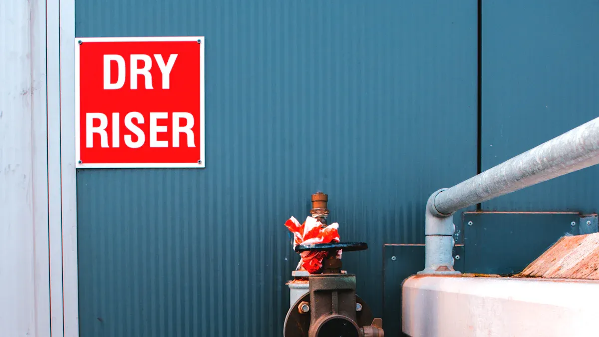
Ensuring Accessible Fire Department Connections
The Fire Department Connection (FDC) is the vital link allowing firefighters to supplement the building's internal water supply. Its location and visibility are critical for a rapid emergency response. Building codes require clear and specific signage at each FDC.
The signage must clearly identify the system it serves. NFPA standards mandate specific lettering to avoid confusion during an emergency.
| System Type | Required Marking (1-inch letters) |
|---|---|
| Sprinkler Only | AUTOSPKR |
| Standpipe Only | STANDPIPE |
| Combined System | STANDPIPE AND AUTOSPKR |
Additional signage requirements include:
- Indicating if a standpipe is a manual wet or manual dry system.
- Displaying the required system pressure if it exceeds 150 psi.
- Clearly defining the specific floors or areas served if the FDC does not supply the entire building.
Finally, facility managers must maintain unobstructed access to all FDCs. A blocked connection can cause catastrophic delays. Common obstructions include:
- Landscaping: Trees, shrubs, and decorative boulders.
- Man-Made Barriers: Parked vehicles, fences, pallets, and temporary walls.
- Debris: Snow, trash, and even wasp or bird nests inside the connections.
Regular inspections ensure these connections remain visible, accessible, and ready for immediate use 24/7.
Integrating and Powering Fire Pumps
A high-rise building's standpipe system is only as effective as the pumps that supply it. Fire pumps are the heart of the water delivery system, providing the necessary pressure and volume to fight a fire on any floor. Proper integration involves precise sizing, careful pump selection, and an unwavering commitment to providing reliable power.
Sizing Pumps for Pressure and Flow
Engineers must correctly size fire pumps to overcome gravity and friction, delivering water at the required pressure and flow rate to the highest and most remote hose connection. An undersized pump will fail to deliver adequate water, while an oversized pump wastes energy and can create dangerously high pressures.
The calculation for the required pump discharge pressure is a methodical process. It adds up all the pressure demands starting from the firefighter's nozzle and working back to the pump. The basic formula includes four key components:
Pump Discharge Pressure = NP + FL + APP + ELEV
- Nozzle Pressure (NP): The pressure required at the nozzle for an effective fire stream.
- Friction Loss (FL): The pressure lost as water moves through hoses, pipes, elbows, and valves. This includes friction from the vertical rise of the standpipe itself.
- Appliance Pressure (APP): The pressure lost through appliances like a ladderpipe or wye connection.
- Elevation (ELEV): The pressure needed to lift the water to the fire floor. Every foot of elevation requires approximately 0.433 psi.
The following table shows how these values combine in different scenarios:
| Component | Example 1 (Master Stream) | Example 2 (Multiple Hoses) |
|---|---|---|
| Nozzle Pressure (NP) | 80 psi | 80 psi |
| Friction Loss (FL) | 84 psi | 129 psi |
| Appliance Pressure (APP) | 10 psi | 20 psi |
| Elevation (ELEV) | 13 psi (30 ft) | 35 psi (80 ft) |
| Total Pump Discharge Pressure | 187 psi | 264 psi |
Flow rate requirements are defined by NFPA 14. For a fully sprinklered high-rise, the standard mandates:
- A minimum of 500 gallons per minute (gpm) for the first standpipe.
- An additional 250 gpm for each subsequent standpipe.
- A maximum required flow of 1,000 gpm.
Selecting a Vertical Turbine Fire Pump
For high-rise applications, the Vertical Turbine Fire Pump is an exceptional choice due to its unique design and operational advantages. Unlike horizontal pumps, this model is ideal for buildings with below-ground water storage tanks.
Key Advantages of a Vertical Turbine Design The motor sits above ground for easy maintenance, while the pumping assembly is submerged in the water source. This configuration optimizes floor space, eliminates the need for priming, reduces noise, and ensures a consistent water supply even from deep tanks.
The TKFLO Diesel Engine Long Shaft Vertical Turbine Fire Pump exemplifies this technology's benefits. It is engineered to meet stringent GB6245-2006 and NFPA standards, ensuring unparalleled reliability. Its advanced hydraulic design and robust construction make it a leading solution for critical fire protection in high-rise buildings. A Vertical Turbine Fire Pump offers superior durability because its submerged components are less susceptible to cavitation, a common cause of pump damage.
Proper installation is paramount for long-term performance. Before installation, teams must verify that the foundation is level, the correct pump model is selected, and all necessary tools are ready. The installation process involves carefully setting the baseplate, lowering and connecting the column and bowl assembly, and precisely aligning the driver. Adhering strictly to NFPA 20 guidelines during setup prevents common mistakes like shaft misalignment or improper grouting that lead to vibration and premature failure.
Securing Reliable Primary and Backup Power
A fire pump is useless without a guaranteed power source. NFPA 20 sets strict criteria for what it considers a "reliable" primary power source for an electric motor-driven pump. The utility provider must have a history of stability, with no unscheduled outages exceeding four continuous hours in the past year. Furthermore, the voltage at the fire pump controller cannot drop more than 15% during motor startup or 5% during a full run.
If the primary power source does not meet these standards, a reliable backup power source is mandatory. For high-rise buildings, this almost always means an on-site diesel generator.
NFPA 25: Diesel Fuel Testing Requirements
8.3.4.1 Diesel fuel shall be tested for degradation no less than annually.
8.3.4.2 If diesel fuel is found to be deficient...the fuel shall be reconditioned or replaced, the supply tank shall be cleaned internally, and the engine fuel filter(s) shall be changed.
High-quality pump systems, like those from TKFLO, integrate powerful diesel engines from reputable brands like Cummins or Deutz. These engines are known for their reliable starting and strong overload capacity. However, the engine's reliability depends entirely on its fuel. Modern diesel fuel can degrade in storage, leading to clogged filters and engine failure during an emergency.
For this reason, NFPA 110 and NFPA 25 mandate rigorous fuel system design and maintenance. Key requirements include:
- Clean Fuel Supply: The system must be designed to keep fuel free of water and contaminants. Galvanized fuel lines are prohibited, as sulfur in diesel can react with the zinc coating and foul the engine.
- Sufficient Storage: Fuel tanks must hold enough fuel for the system's required runtime, but not so much that the fuel sits for years and degrades.
- No Automatic Valves: NFPA 110 prohibits automatically actuated valves in the fuel supply line to prevent an accidental shutoff of fuel to life-safety equipment like a Vertical Turbine Fire Pump.
Ultimately, combining a robust pump with a meticulously maintained power and fuel system is the only way to ensure water will flow when the alarm sounds.
Securing an Adequate On-Site Water Supply
A powerful pump and a well-designed standpipe are ineffective without a sufficient, dedicated water source. On-site water storage tanks provide this critical supply, ensuring firefighters have the water they need, independent of the municipal system. Proper engineering involves calculating the right volume, placing tanks strategically, and protecting them from degradation.
Calculating Water Storage Volume
Engineers calculate the required water storage volume based on the building's specific fire risk. NFPA 13, the Standard for the Installation of Sprinkler Systems, classifies buildings by their hazard level. This classification directly determines the minimum duration the water supply must last.
- Light Hazard Occupancies: Require a water supply duration of at least 30 minutes.
- Ordinary Hazard Occupancies: Need a water supply lasting from 60 to 90 minutes.
The total required volume is the product of the system's flow demand (sprinkler demand plus hose stream allowance) and the required duration. For example, a system demanding 250 gallons per minute (gpm) for a 30-minute duration requires a 7,500-gallon tank (250 gpm x 30 min).
Strategically Placing Water Tanks
The location of a water tank significantly impacts structural loads, hydraulic pressure, and system cost. Building designers typically choose between placing tanks on the roof or at intermediate service levels. Each strategy offers distinct advantages and disadvantages.
| Feature | Intermediate Level Tanks | Roof Tanks |
|---|---|---|
| Hydraulic Pressure | Provides adequate pressure without extra valves. | May require pressure-reducing valves for lower floors. |
| Structural Impact | Distributes weight across multiple floors. | Concentrates a massive load at the top of the building. |
| Power Dependency | More sensitive to electricity outages. | Can supply lower floors via gravity during a power failure. |
A Smart Hybrid Approach Some modern designs use a hybrid model for maximum efficiency. For instance, the Motive Apartments in Perth, Australia, use a small basement pump to keep a rooftop tank full. Upper floors are served by small booster pumps, while lower floors receive water via gravity. This strategy saves electricity and ensures water access even during power outages.
Preventing Sediment and Corrosion
Water storage tanks must remain free of corrosion and sediment to ensure system reliability. Corrosion weakens the tank structure, while sediment can clog pipes and foul pump components. Facility managers must implement a proactive maintenance and protection plan.
Interior tank surfaces require robust protective coatings to form a barrier between the water and the steel.
- Epoxy Linings: Modern, high-solids epoxy linings that are NSF 61 certified offer excellent, long-lasting protection and are safe for potable water systems.
- Ceramic Coatings: Chemically bonded phosphate ceramic coatings provide superior resistance in harsh environments by bonding directly with the metal substrate.
Adherence to standards like AWWA D102 ensures coatings are applied correctly for a service life that can approach thirty years. Additionally, proper tank design incorporates features like anti-vortex plates at the pump suction inlet. Maintaining adequate clearance between this plate and the tank floor is crucial to prevent sediment from being drawn into the fire protection system.
Executing a Rigorous Maintenance and Testing Protocol
A fire protection system's design is only as good as its maintenance. Building owners and facility managers must execute a rigorous inspection, testing, and maintenance (ITM) protocol to ensure every component functions as intended. This proactive approach, guided by NFPA standards, is the only way to guarantee system reliability during an emergency.
Following Daily, Weekly, and Monthly Checks
Consistent visual inspections prevent minor issues from becoming catastrophic failures. Facility personnel should regularly check for common deficiencies that can compromise the system.
- Pump Room Conditions: The room must maintain adequate heat (above 40°F for diesel with heaters) and have freely operating ventilation louvers.
- Hose Assemblies: Hoses require inspection for mildew, cuts, or deterioration. Hose nozzles should be present, unobstructed, and operate smoothly.
- Cabinets and Connections: Hose cabinets must open fully, and Fire Department Connections (FDCs) must remain visible and accessible, with caps in place and swivels that rotate freely.
- Gauges: Technicians should replace or recalibrate gauges every five years to ensure they remain accurate within 3 percent of their full scale.
Conducting Annual Full Flow Tests
The annual full flow test is a critical performance benchmark for the fire pump. Qualified personnel must conduct this test to verify the pump meets its original design specifications. The procedure involves several key steps:
- Prepare the System: Technicians connect hoses to approved test devices or a designated discharge point.
- Measure Flow Rates: They operate the pump to measure its output at three distinct conditions: churn (no flow), 100% of its rated capacity, and 150% of its rated capacity.
- Record Data: During the test, they record crucial data, including pump speed, suction and discharge pressures, and electric motor voltage and current.
- Analyze Results: The collected data is plotted and compared against the pump's factory specifications and previous test results to confirm performance.
Required Run Times ⏱️ During the annual test, electric motor-driven pumps must run for at least 10 minutes, while diesel engine-driven pumps must run for a minimum of 30 minutes.
Adhering to NFPA 25 for System Integrity
NFPA 25, the Standard for the Inspection, Testing, and Maintenance of Water-Based Fire Protection Systems, is the authoritative guide for system integrity. Adherence is not optional; it is a legal requirement in many jurisdictions. Failure to comply can lead to hefty fines, canceled insurance, and severe legal liability. The standard mandates a comprehensive schedule of tasks.
| Key ITM Requirement | Frequency | NFPA 25 Section (2017) |
|---|---|---|
| Main Drain Test | Annually | 13.2.5 |
| Hydrostatic Test (Piping) | Every 5 years | 6.3.2.1 |
| Flow Test (Automatic System) | Every 5 years | 6.3.1.1 |
| Valve Supervisory Switch Test | Semiannually | 13.3.3.5 |
Ultimately, these protocols ensure that every valve, pipe, and pump is ready to perform, protecting both property and lives.
The foundation of high-rise fire safety rests on three pillars: a well-designed standpipe system, correctly sized pumps like a Vertical Turbine Fire Pump with backup power, and sufficient on-site water storage. However, design alone is insufficient. As tragedies like the Grenfell Tower fire demonstrate, system failures often stem from inadequate inspections.
Integrated testing is critical to ensuring that a building’s fire and life safety systems work together in a coordinated fashion.
Ultimately, combining robust engineering with non-negotiable adherence to NFPA 25 maintenance protocols is the only proven method to guarantee water access when it is needed most.
FAQ
Why is a Vertical Turbine Fire Pump ideal for high-rises?
A Vertical Turbine Fire Pump excels in high-rise applications. Its motor sits above ground for easy maintenance. The submerged pump assembly draws water directly from below-ground tanks. This design saves valuable floor space and ensures a constant, reliable water source without requiring priming.
What is the most critical NFPA standard for system reliability?
NFPA 25 is the most critical standard for ensuring system readiness. It mandates the schedule for inspection, testing, and maintenance (ITM). Following NFPA 25 protocols confirms that all fire protection components, including pumps and standpipes, will function correctly during an emergency.
Why is backup power for a fire pump essential?
Backup power guarantees the fire pump operates during a utility outage. A fire can easily damage a building's primary electrical grid. A dedicated diesel generator, like those integrated with TKFLO systems, provides an independent power source, making it a life-safety necessity.
How often must a fire protection system be tested?
System testing follows a strict schedule defined by NFPA 25.
- Personnel perform visual checks daily, weekly, and monthly.
- Technicians conduct a full flow test on the fire pump annually.
- Major components like piping require hydrostatic tests every five years.
See Also
Fortifying Doors and Hinges: Essential Protection Against Wildfires and Floods
Crucial Safety Protocols for Secure Nitric Acid Storage and Handling
Simple Maintenance Routines to Avoid Costly Dumbwaiter Elevator Malfunctions
Benefits of Selecting a Self-Priming Water Pump for Your System Needs
Comparing EHEDG Guidelines and 3A SSI Standards for Optimal Hygienic Design