Essential Steps to Fix PCB-Mounting Current Transformer Failures
You can fix failures in a PCB-mounting Current Transformer by following clear steps. Start with careful identification of symptoms, then move to troubleshooting and repairs. Use a systematic approach at every stage. Always think about safety first. When you handle a precision current transformer, check connections and inspect for damage. Stay alert and follow proper procedures to protect yourself and your equipment.
Key Takeaways
- Identify symptoms of transformer failure early, such as overheating or unusual noises. Regular inspections can prevent bigger issues.
- Always prioritize safety by powering down the circuit and using proper personal protective equipment (PPE) before starting repairs.
- Conduct thorough visual inspections for physical damage, burn marks, and solder joint issues. This step is crucial for effective troubleshooting.
- Use diagnostic tools like multimeters and thermal cameras to test connections and measure signals. These tools help pinpoint problems quickly.
- Implement preventive maintenance by scheduling regular inspections and cleaning. This practice extends the lifespan of your transformer.
PCB-mounting Current Transformer Failure Symptoms and Causes
Typical Signs of Transformer Failure
You can spot a failing PCB-mounting Current Transformer by watching for several clear signs. These symptoms often show up during normal operation or routine checks.
- You may notice the transformer gets hotter than usual.
- Sometimes, you hear buzzing or humming sounds that were not there before.
- The device might stop working or give wrong readings.
- You could see burn marks or smell something burning near the transformer.
- In some cases, the circuit trips or shuts down without warning.
Technical studies show that internal defects, like short circuits in the windings or core, often cause these problems. External factors, such as lightning strikes or strong vibrations, can also damage the transformer. Poor ventilation can make the transformer overheat. If you see any of these signs, you should check the transformer right away.
Tip: Regular inspections help you catch these symptoms early and prevent bigger problems.
Frequent Causes of Issues
Many things can cause a PCB-mounting Current Transformer to fail. Some of the most common reasons include:
- Temperature changes that stress the transformer
- Exposure to moisture, which can cause corrosion and lead to short circuits
- Mechanical stress from vibrations or loose mounting
- Solder joint fatigue, which weakens connections over time
- Dielectric breakdown, which reduces insulation effectiveness and increases the risk of power loss
Environmental factors play a big role. For example, moisture can break down insulation and cause corrosion. Mechanical stress can damage the transformer’s body or loosen its connections. When insulation fails, short circuits and power losses become more likely.
Research shows that bushing and winding problems account for many transformer failures. Regular maintenance and careful handling can help you avoid these issues.
PCB-mounting Current Transformer Safety Precautions
Power Down and Isolate the Circuit
You must always turn off the power before you start working. This step keeps you safe from electric shock. Disconnect the circuit from its power source. Use a lockout device if you have one. Make sure no one can turn the power back on while you work. You should also isolate the circuit by removing any connections to other devices. This action helps prevent accidental current flow. Many industry standards require these steps for safety. The table below shows some important standards:
| Standard Code | Description |
|---|---|
| IPC-2221 | Generic PCB Design Standard |
| IEC 61558 | Safety of Power Transformers |
| UL 5085 | Industrial Control Equipment |
Tip: Always double-check that the circuit is off before you touch any part.
Use Proper Personal Protective Equipment (PPE)
You need to wear the right gear to protect yourself. Gloves shield your hands from electric shock and sharp edges. Respirators help you avoid breathing in harmful fumes. Protective clothing keeps your skin safe from burns. For electrical work, choose insulated gloves and safety glasses. Flame-resistant clothing and non-conductive footwear add extra protection. You can also wear a hard hat rated for electrical hazards. Some experts recommend Class 0, 14-inch rubber gloves with leather protectors. Electrical hazard-rated boots help keep you safe.
- Gloves
- Respirators
- Protective clothing
- Insulated gloves
- Safety glasses
- Flame-resistant clothing
- Non-conductive footwear
- Electrical-related hard hat
- Rubber insulated gloves
- Electrical hazard-rated boots
⚡ Note: Never skip PPE, even for quick checks.
Discharge Stored Energy
You should always discharge stored energy before you begin repairs. Capacitors and coils can hold a charge even after you turn off the power. Use a discharge tool to release this energy safely. Touch the tool to the terminals and wait for the charge to drop. This step prevents shocks and protects your equipment. Always check with a meter to make sure no voltage remains. If you skip this step, you risk injury or damage.
Alert: Discharging stored energy is a must for safe troubleshooting of a PCB-mounting Current Transformer.
PCB-mounting Current Transformer Visual Inspection
Inspect for Physical Damage
Start your inspection by looking for any physical damage on the transformer and the surrounding area. You might see cracks, dents, or broken parts. Sometimes, the transformer case looks swollen or warped. These signs often mean the transformer has overheated or suffered a mechanical shock. If you spot any loose or missing mounting screws, fix them right away. A transformer that moves on the board can cause more problems. Use a flashlight to check hard-to-see spots. Pay close attention to the pins and leads. Bent or corroded pins can cause poor connections.
Tip: Take clear photos of any damage you find. This helps you track changes over time.
Check for Burn Marks or Odors
Burn marks or strange smells often point to serious problems. Look for dark spots or discoloration on the transformer, PCB, or nearby components. These marks usually show where heat has built up. If you smell something burnt, try to find the source. Sometimes, the smell comes from melted insulation or overheated solder. Do not ignore these signs. They often mean the transformer or another part has failed. If you find burn marks or a strong odor, you should stop and plan a repair.
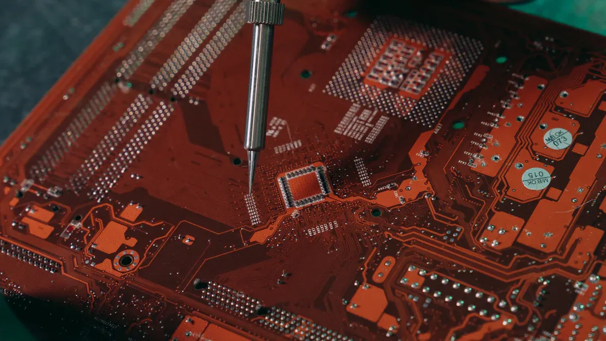
Examine Solder Joints and PCB Traces
Carefully check the solder joints and PCB traces around the transformer. Bad solder joints can cause poor connections or even open circuits. Use a magnifying glass to spot cracks, cold joints, or missing solder. Traces that look lifted or burned may not carry current well. For best results, follow these inspection steps:
- Perform a thorough visual inspection to spot soldering issues, misplaced components, or poor mechanical fit.
- Use Automated Optical Inspection (AOI) systems if you have access. AOI helps you find problems with solder joints and traces quickly.
- Try Automated X-Ray Inspection (AXI) for hidden solder defects, especially if your board uses complex components.
If you find any faults, mark them for repair. Good solder joints and clean traces help your PCB-mounting Current Transformer work safely and reliably.
PCB-mounting Current Transformer Testing and Diagnosis
Testing and diagnosis help you find the root cause of problems in your PCB-mounting Current Transformer. You need to check wiring, measure signals, and look for open or short circuits. Each step gives you clues about what is wrong and how to fix it.
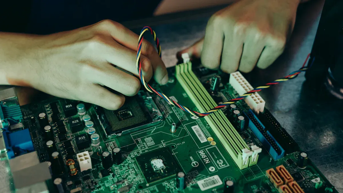
Verify Wiring and Connections
You should start by checking all wiring and connections. Loose wires or poor connections can cause your transformer to fail. Use your eyes first. Look for wires that are not attached or connectors that seem out of place. If you see anything odd, mark it for further testing.
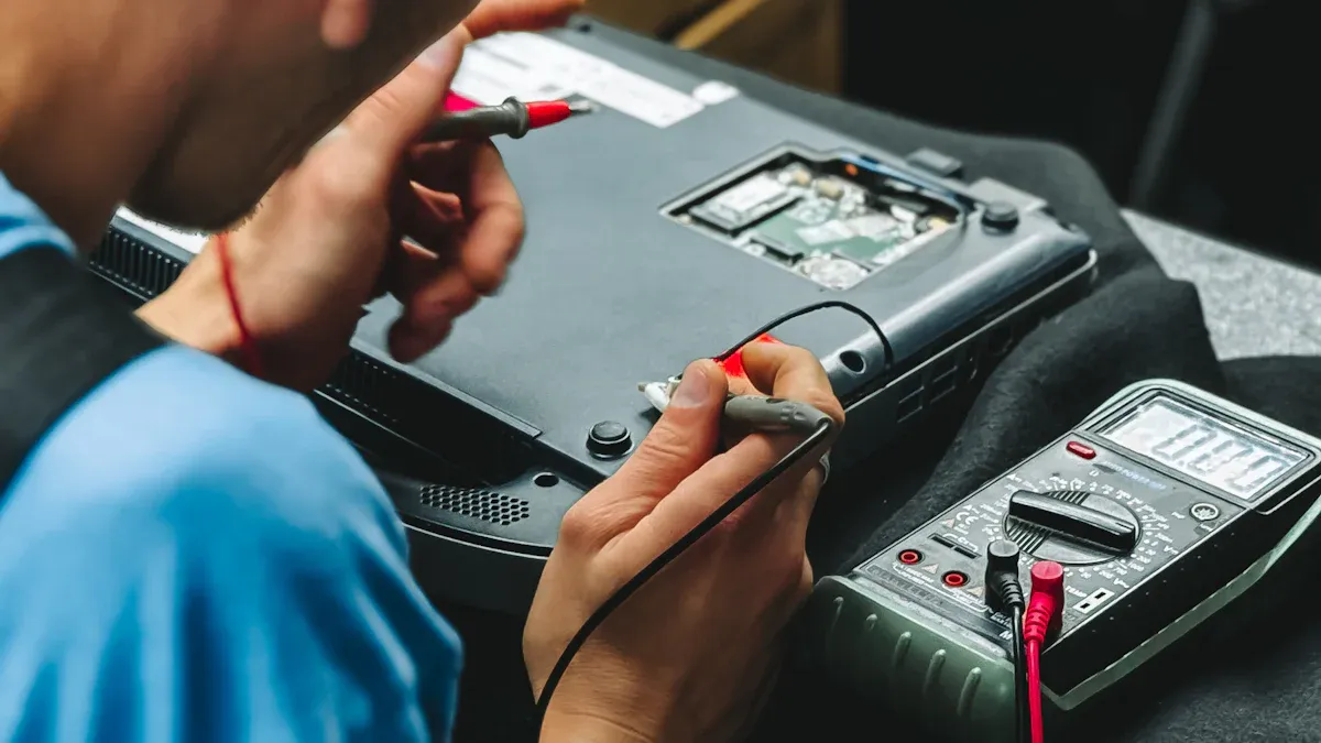
Next, use diagnostic tools to make sure everything works as it should. The table below shows some tools you can use and what they do:
| Tool | Purpose |
|---|---|
| Multimeter | For continuity and short circuit testing |
| Oscilloscope | For signal analysis and identifying issues |
| Thermal Camera | For detecting overheating components |
A multimeter helps you check if electricity flows through the wires. An oscilloscope lets you see the shape of the signals. A thermal camera shows you if any part gets too hot. These tools make your job easier and help you find problems quickly.
Tip: Always test connections after you move or repair any wires. This step helps you avoid future failures.
Measure Input and Output Signals
You need to measure the input and output signals to see if your PCB-mounting Current Transformer works correctly. Use an oscilloscope to look at the signal waveforms. The input signal should match the expected current. The output signal should show the correct transformation ratio.
If you see strange shapes or missing signals, you may have a problem inside the transformer. Sometimes, the output signal looks weak or noisy. This issue can mean the transformer is damaged or the circuit has a fault. Compare your readings to the specifications in the datasheet. If the numbers do not match, you need to investigate further.
⚡ Note: Always measure signals with the right settings on your test equipment. Wrong settings can give you false results.
Check for Open or Short Circuits
Open or short circuits can stop your transformer from working. You can use several techniques to find these problems:
- Visual Inspection: Look for broken traces, burnt spots, or missing parts on the PCB.
- Multimeter Testing: Measure continuity and resistance. If you see zero resistance, you may have a short circuit. If you see infinite resistance, you may have an open circuit.
- Thermal Imaging: Use a thermal camera to spot hotspots. Hot areas can mean too much current flows through a short circuit.
If you find an open circuit, check for broken wires or damaged solder joints. If you find a short circuit, look for solder bridges or melted components. Fix these problems before you test the transformer again.
🔍 Alert: Never ignore signs of open or short circuits. These faults can damage your PCB-mounting Current Transformer and other parts of your system.
PCB-mounting Current Transformer Fixes for Common Issues
Repair or Replace Loose Connections
Loose connections can cause your transformer to fail or give wrong readings. You need to fix these problems right away to keep your circuit safe and reliable. Here are the most common steps you should follow:
- Inspect the board. Look for any loose or broken connections around the transformer.
- Reseat or realign the component. Make sure the transformer sits flat on the PCB and the pins line up with the pads.
- Reflow the solder. Use a soldering iron to melt and reset the solder on each pin. This step helps restore a strong electrical connection.
- Fix lifted pads or traces if you see them. Carefully press them back into place and secure them with fresh solder.
- Clean the area. Remove any leftover flux or debris with isopropyl alcohol and a soft brush.
- Replace the transformer if you see damage that you cannot repair. Sometimes, a new part is the safest choice.
Tip: Always check your work with a multimeter after you finish repairs. This step helps you catch any missed problems.
Correct Incorrect Wiring
Incorrect wiring can cause your transformer to work the wrong way or even damage your circuit. You need to make sure every wire connects to the right place. Follow these steps to correct wiring mistakes:
- Check the current flow direction. The current must match the markings and wiring diagram for your transformer.
- If you see reversed polarity, reinstall the transformer so the current flows from P1 to P2.
- If you cannot reinstall the transformer, swap the S1 and S2 connections. Connect S1 (red wire) to the negative terminal and S2 (black wire) to the positive terminal.
- If your meter shows negative readings, you likely have reversed polarity.
- Swapping the S1 and S2 wires usually fixes this problem.
⚡ Alert: Always double-check the wiring before you power up the circuit. Incorrect wiring can cause damage or false readings.
Address Transformer Saturation
Transformer saturation happens when the core cannot handle any more magnetic flux. This problem can cause non-linear readings and even damage your transformer. You might see this issue if you exceed the volt-second rating or if a short-circuit current flows through the transformer.
- Non-linearities often show up during saturation.
- Exceeding the volt-second rating can push the core past its limit.
- High short-circuit currents can also cause saturation.
To prevent saturation, you should understand the volt-second rating for your transformer. Make sure the core does not go past its flux limit. You can also use a transformer with a larger core area or lower the burden resistance. These steps help keep your transformer working in a linear range, even at high currents.
Note: Always check the datasheet for your transformer’s ratings. Staying within these limits helps you avoid saturation and keeps your circuit safe.
Replace Damaged Components
You need to replace damaged components to restore your PCB-mounting current transformer. Damaged parts can cause errors, overheating, or even complete failure. You can follow these steps to make sure you do the job right.
-
Identify the Damaged Component
Use your eyes and tools to find the part that does not work. Look for cracks, burns, or melted plastic. You can check the datasheet to match the part number and shape. -
Remove the Faulty Part
Use a soldering iron to heat the pins. Gently pull the component out with tweezers. Try not to damage the PCB pads or traces. If the part sticks, add a little solder to help it come loose. -
Clean the Area
Wipe away old solder and debris with isopropyl alcohol. Use a soft brush to clean the pads. Clean pads help you make a strong connection with the new part. -
Install the New Component
Place the new part in the correct spot. Make sure the pins line up with the pads. Solder each pin carefully. Do not use too much solder. You want a shiny, smooth joint. -
Check Your Work
Use a multimeter to test the new connections. Make sure the part sits flat and does not wiggle. Look for any solder bridges or cold joints.
🛠️ Tip: Always use the same type and rating as the original component. This step keeps your circuit safe and reliable.
Common Damaged Components in PCB-Mounting Current Transformers
| Component | Signs of Damage | Replacement Advice |
|---|---|---|
| Transformer Core | Cracks, burns, warping | Use exact match for size and type |
| Solder Joints | Dull, cracked, missing | Reflow or add fresh solder |
| PCB Traces | Lifted, burnt, broken | Repair with wire or copper tape |
| Connectors | Bent, corroded, loose | Replace with new connectors |
You should always check the datasheet before you buy a new part. The wrong part can cause more problems. If you cannot find the exact match, ask the supplier for help.
⚡ Alert: Never rush when you replace components. Careful work prevents new failures and keeps your transformer working for a long time.
You can fix most problems by replacing damaged parts. You keep your PCB-mounting current transformer safe and working well. Careful repairs help you avoid future breakdowns.
PCB-mounting Current Transformer Post-Repair Testing and Preventive Maintenance
Confirm Proper Operation
After you finish repairs, you need to make sure your PCB-mounting Current Transformer works as it should. Follow these steps to confirm proper operation:
- Choose a transformer with the same model and correct polarity. Make sure it matches the volt-ampere rating.
- Check relay protection settings and meter multipliers if you replaced transformers in a group.
- Inspect the new secondary cable. It must handle the load current and have good insulation resistance.
- Measure the polarity of the whole secondary circuit before you turn on the power.
- If you use oil-filled transformers, check for clean surfaces, enough oil, and no leaks.
- Look for cracks or damage on all insulating materials.
- Tighten all screws. Make sure the primary and secondary connections have good contact.
- Ground the casing and secondary circuit properly.
- Plan preventive tests every one to two years. Repeat these checks during each test.
- Make sure the secondary circuit is not open. Check for any loose wires.
🛠️ Tip: Careful checks after repair help you avoid future problems and keep your system safe.
Monitor for Recurring Problems
You should keep an eye on your transformer after repairs. Watch for signs that problems might return. Use these steps to help you:
- Check the transformer for heat, noise, or odd smells during operation.
- Use a thermal camera to spot overheating early.
- Record your test results and compare them over time. This helps you see changes quickly.
- Set up a schedule to review your transformer’s performance every few months.
If you notice the same issue more than once, look for deeper causes. Sometimes, a hidden problem can cause repeated failures.
Implement Preventive Measures
You can lower the risk of future failures by using good preventive maintenance. Try these proven steps:
- Regular inspection: Look for damage and use infrared thermography to find hot spots.
- Cleaning and maintenance: Keep the transformer clean. Make sure cooling fans or systems work well.
- Oil testing and analysis: If your transformer uses oil, test it often to check for contamination or breakdown.
⚡ Note: Preventive care keeps your transformer working longer and helps you avoid costly repairs.
You can fix PCB-mounting current transformer failures by following a clear process. Start with these expert-recommended steps:
- Check for physical damage and overheating.
- Test polarity to confirm correct orientation.
- Use an insulation tester for resistance checks.
- Clean dust and contaminants.
- Calibrate the transformer with a trusted standard.
- Listen for unusual noises and consult a professional if needed.
Safety and preventive maintenance matter. Regular monitoring and condition-based care help your transformer last longer. The table below shows how maintenance extends lifespan and reduces costs:
| Evidence Description | Impact on Lifespan |
|---|---|
| Continuous monitoring identifies early failures. | Timely maintenance extends operational life. |
| Routine analysis ensures transformers meet design life. | Reliability and longevity increase, even in harsh settings. |
A methodical approach keeps your equipment reliable and safe. Stay alert, follow each step, and protect your system for years to come.
FAQ
What tools do you need to test a PCB-mounting current transformer?
You need a multimeter, oscilloscope, and thermal camera. These tools help you check connections, measure signals, and find overheating parts.
How often should you inspect your current transformer?
You should inspect your transformer every six months. Regular checks help you find problems early and keep your system safe.
Can you fix a burnt PCB trace yourself?
You can repair a burnt trace with copper tape or wire. Clean the area first. Use fresh solder to connect the new trace.
What should you do if your transformer keeps overheating?
Tip: Check for blocked airflow and clean dust. Make sure the transformer matches your circuit’s rating. Replace it if overheating continues.
How do you know if the transformer is installed with correct polarity?
| Method | What to Check |
|---|---|
| Meter Reading | Positive value |
| Wiring Diagram | P1 to P2 direction |
| Signal Output | Matches datasheet |
Check these signs to confirm correct polarity.
See Also
Innovative Solutions for Smart Meter Current Transformers
Essential Tips for Choosing the Right Power Transformer
Unexpected Methods for Sulfur Recovery Catalyst Troubleshooting