A Practical Comparison of Current Transformers for Measurement vs Protection

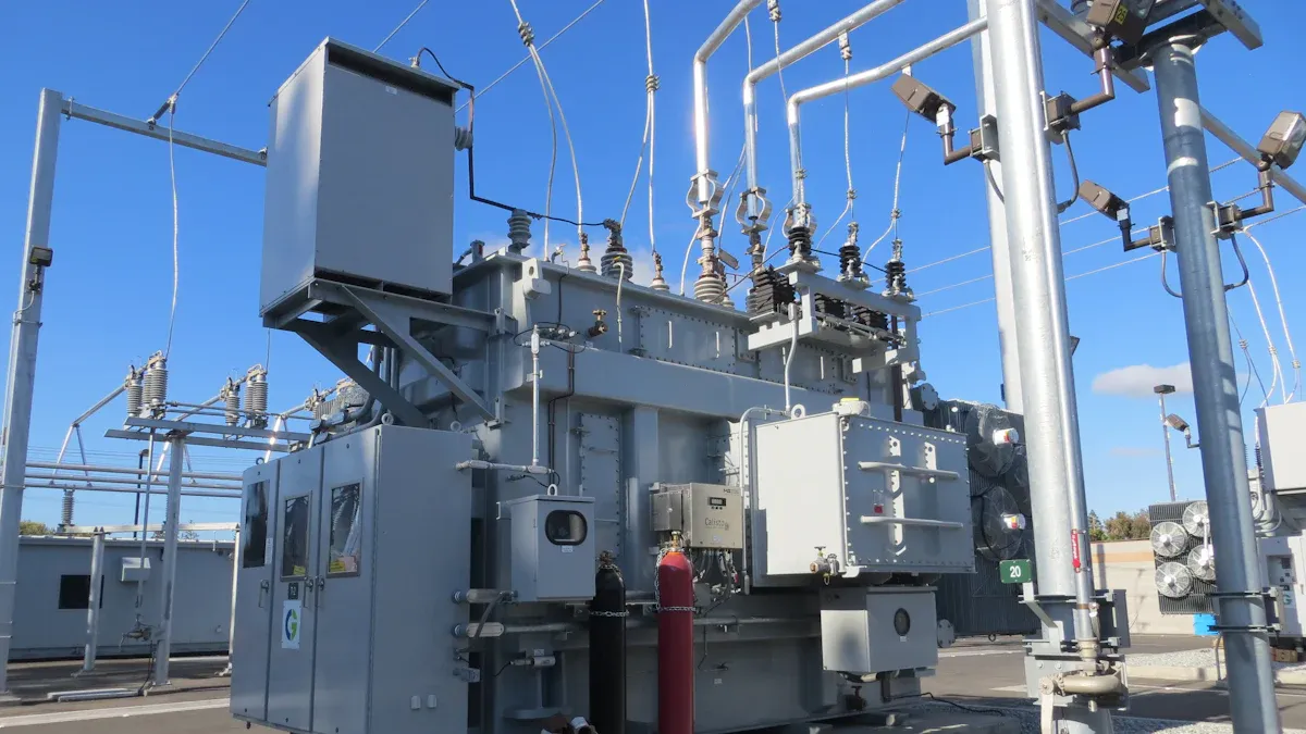
A Current Transformer serves one of two distinct roles. Measurement CTs provide high accuracy within normal current ranges for billing and metering. In contrast, protection CTs ensure dependable operation during high-current electrical faults to safeguard equipment. This functional divide dictates the component's design, accuracy, and ultimate application. The industry's expansion is clear, a trend that every Current Transformer manufacturer and Current Transformer supplier recognizes.
| Metric | Value |
|---|---|
| Global Market Size (2024) | USD 2.4 Billion |
| Projected Market Size (2034) | USD 4.4 Billion |
| Compound Annual Growth Rate (CAGR) (2025-2034) | 6.2% |
Key Takeaways
- Current Transformers (CTs) have two main jobs: measuring electricity for billing or protecting equipment from damage.
- Measurement CTs are very accurate for normal electricity use. Protection CTs work best during big electrical problems to keep things safe.
- Using the wrong type of CT can be dangerous. It can cause equipment to break or lead to wrong electricity bills.
- Measurement CTs and Protection CTs are built differently inside. This helps them do their specific jobs well.
- Always pick the right CT for the job. This keeps people safe, protects expensive machines, and makes sure electricity bills are correct.
Core Function: Precision for Metering vs. Reliability for Safety
The fundamental difference between a measurement and a protection Current Transformer lies in its intended operational range. One is designed for financial precision under normal conditions, while the other is engineered for failsafe reliability during system emergencies. This core distinction influences every aspect of their design and application.
Measurement CTs: The Basis of Accurate Billing
Measurement CTs are the financial backbone of an electrical system. Their primary role is to provide a highly accurate, scaled-down representation of the primary current to metering devices. Utilities and facility managers rely on this precision for correct energy billing and consumption monitoring. These CTs operate with exceptional accuracy, but only within the normal operating current of the system, typically up to 120% of their rated value.
To ensure this level of financial accuracy, their performance is governed by strict national and international standards. Key examples include:
- ANSI C12.1-2024: An American standard that sets performance criteria for electricity meters and associated transformers in high-accuracy classes like 0.1, 0.2, and 0.5.
- IEC 61869-1 ED2: An international standard that defines accuracy requirements for instrument transformers, ensuring consistent and reliable measurements, especially in high-voltage systems.
Protection CTs: The Sentinel for Your System
Protection CTs act as the vigilant guardians of electrical equipment. Their job is not to measure normal currents with precision but to reliably detect and communicate dangerous overcurrents during faults. When a short circuit occurs, a protection CT must accurately transform the massive fault current for the protective relay. The relay then signals a circuit breaker to trip and isolate the fault.
⚡ Critical Speed: Protective relays must operate within fractions of a second to prevent catastrophic equipment damage. A typical overcurrent relay might be set to trip in just 0.2 seconds. This rapid response, governed by standards like ANSI C37.90 and IEC 60255, is only possible if the CT provides a dependable signal without saturating under extreme stress.
This function prioritizes reliability over precision. A protection CT is built to withstand immense currents and deliver a usable signal, ensuring the safety of personnel and the longevity of expensive assets like generators and transformers.
Technical Deep Dive: Core, Saturation, and Burden
The functional differences between measurement and protection CTs originate from their physical construction. The choice of core material, the definition of accuracy, and the capacity to handle electrical load (burden) are three technical pillars that define their performance and application.
Core Material and Saturation Behavior
At the heart of every Current Transformer is a magnetic core. This core's material and design dictate how the transformer behaves under different current levels.
-
Measurement CTs use cores made from materials with high magnetic permeability, such as grain-oriented silicon steel. This material allows the CT to conduct magnetic flux very efficiently, which is essential for achieving high accuracy at low, normal operating currents. Silicon steel offers high permeability and low core loss, minimizing energy dissipation and making it a cost-effective choice for these components. However, this high permeability comes with a trade-off. The core saturates, or becomes magnetically "full," at relatively low overcurrents (e.g., 150-200% of the rated current). This saturation is a deliberate design feature that acts as a protective mechanism, limiting the voltage and current passed to the delicate and expensive metering equipment connected to it.
-
Protection CTs are engineered for the opposite behavior. They must avoid saturation during massive fault currents to ensure a protective relay receives an accurate signal. To achieve this, they use cores made from lower-grade silicon steel or incorporate small air gaps in the core. This design lowers the magnetic permeability, requiring a much stronger magnetic field (and thus a much higher primary current) to cause saturation. This ensures the CT can faithfully reproduce fault currents many times its nominal rating for the relay to analyze.
Accuracy Class and Error Limits
A CT's accuracy class is a standardized rating that quantifies its maximum permissible error. The definition of this "error" differs significantly between measurement and protection types.
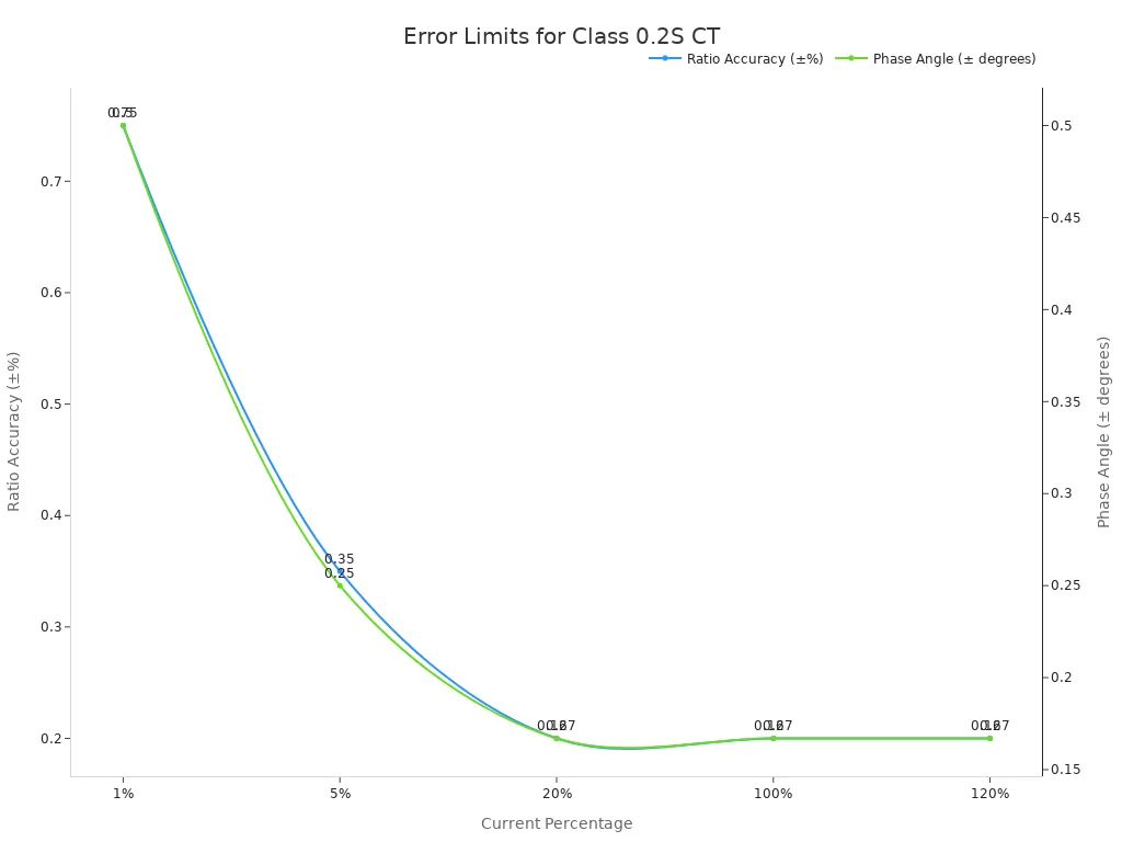
Measurement CT Accuracy For measurement CTs, accuracy is defined by ratio error and phase angle error within the normal operating range (typically 1% to 120% of rated current). A lower class number signifies higher precision. For example, a Class 0.2S CT is designed for high-precision billing. Its error limits are extremely tight, especially at low currents where residential or commercial loads often operate.
According to the IEC 61869-2 standard, a Class 0.2S CT must adhere to the following limits:
| Current (% of Rated) | Maximum Ratio Error (±%) | Maximum Phase Displacement (±Minutes) |
|---|---|---|
| 1% | 0.75 | 30 |
| 5% | 0.35 | 15 |
| 20% | 0.2 | 10 |
| 100% | 0.2 | 10 |
| 120% | 0.2 | 10 |
Protection CT Accuracy Protection CT accuracy is not about precision billing but about predictable performance during a fault. Its accuracy is defined by a "composite error" at a specified multiple of its rated current. A common protection class is 5P10. This designation breaks down as follows:
- 5: The composite error will not exceed 5% at the accuracy limit.
- P: This letter designates it as a Protection class CT.
- 10: This is the Accuracy Limit Factor (ALF). It means the CT will maintain its specified accuracy up to 10 times its rated primary current.
In short, a 5P10 CT guarantees that when the primary current is 10 times its normal rating, the signal sent to the relay is still within 5% of the ideal value, ensuring the relay makes a correct trip decision.
Burden and VA Rating
Burden is the total electrical load connected to the CT's secondary terminals, measured in Volt-Amperes (VA) or ohms (Ω). Every device and wire connected to the CT contributes to this load. Exceeding a CT's rated burden will degrade its accuracy.
The total burden is the sum of the impedances of all components in the secondary circuit:
- The CT's own secondary winding resistance.
- The resistance of the lead wires connecting the CT to the device.
- The internal impedance of the connected device (meter or relay).
💡 Calculating Total Burden: An engineer can calculate the total burden using the formula:
Total Burden (Ω) = CT Winding R (Ω) + Wire R (Ω) + Device Z (Ω)For instance, if a CT's secondary winding resistance is 0.08 Ω, the connecting wires have 0.3 Ω of resistance, and the relay has an impedance of 0.02 Ω, the total circuit burden is 0.4 Ω. This value must be less than the CT's rated burden for it to operate correctly.
Measurement CTs typically have low VA ratings (e.g., 2.5 VA, 5 VA) because they connect to high-impedance, low-consumption metering devices over short distances. Protection CTs require much higher VA ratings (e.g., 15 VA, 30 VA) because they must supply enough power to operate the lower-impedance, higher-consumption coils of a protective relay, often over much longer cable runs. Incorrectly matching the CT's burden rating to the actual circuit load is a common source of error in both metering and protection schemes.
Understanding the Knee Point Voltage
The Knee Point Voltage (KPV) is a critical parameter exclusive to protection CTs. It defines the upper limit of a CT's useful operating range before its core begins to saturate. This value is essential for ensuring a protective relay receives a reliable signal during a high-current fault.
Engineers determine the KPV from the CT's excitation curve, which plots the secondary exciting voltage against the secondary exciting current. The "knee" is the point on this curve where the core's magnetic properties change dramatically.
The IEEE C57.13 standard provides a precise definition for this point. For a non-gapped core CT, the knee point is where a tangent to the curve forms a 45-degree angle with the horizontal axis. For a gapped core CT, this angle is 30 degrees. This specific point marks the onset of saturation.
When a CT operates below its knee point voltage, its core is in a linear magnetic state. This allows it to accurately reproduce the fault current for the connected relay. However, once the secondary voltage exceeds the KPV, the core enters saturation. Saturation, often driven by large AC currents and DC offsets during a fault, causes the CT's magnetizing impedance to drop significantly. The transformer can no longer faithfully reflect the primary current to its secondary side.
The relationship between KPV and protection reliability is direct and crucial:
- Below the knee point: The CT core operates linearly. It provides an accurate representation of the fault current to the protective relay.
- Above the knee point: The core saturates. This leads to a large increase in magnetizing current and non-linear operation, meaning the CT no longer accurately reflects the true fault current.
- Relay Operation: Protective relays need an accurate signal to operate correctly. If a CT saturates before the relay can make a decision, the relay may fail to detect the fault's true magnitude, leading to a delayed trip or a complete failure to operate.
- System Safety: Therefore, the CT's knee point voltage must be sufficiently higher than the maximum secondary voltage expected during a fault. This ensures the relay receives a dependable signal to protect expensive equipment.
Engineers calculate the required KPV to ensure the CT remains unsaturated under the worst-case fault conditions. A simplified formula for this calculation is:
Required KPV ≥ If × (Rct + Rb)
Where:
If= Maximum secondary fault current (Amps)Rct= CT secondary winding resistance (Ohms)Rb= Total burden of the relay, wiring, and connections (Ohms)
Ultimately, the Knee Point Voltage serves as the primary indicator of a protection CT's ability to perform its safety function under extreme electrical stress.
Decoding Current Transformer Nameplate Designations
A Current Transformer nameplate contains a compact code that defines its performance capabilities. This alphanumeric designation is a shorthand language for engineers, specifying the component's accuracy, application, and operational limits. Understanding these codes is essential for selecting the correct device.
Interpreting Measurement CT Classes (e.g., 0.2, 0.5S, 1)
Measurement CT classes are defined by a number that represents the maximum allowable percentage error at the rated current. A smaller number indicates a higher degree of precision.
- Class 1: Suitable for general panel metering where high precision is not critical.
- Class 0.5: Used for commercial and industrial billing applications.
- Class 0.2: Required for high-accuracy revenue metering.
Some classes include the letter 'S'. The 'S' designation in IEC measurement CT classes, such as 0.2S and 0.5S, signifies high accuracy. This particular classification is generally employed in tariff metering applications where precise measurements are critical, especially at the lower end of the current range.
Interpreting Protection CT Classes (e.g., 5P10, 10P20)
Protection CT classes use a three-part code that describes their behavior during a fault. A common example is 5P10.
Breaking Down the 5P10 Code:
- 5: This first number is the maximum composite error in percent (5%) at the accuracy limit.
- P: The letter 'P' in a classification like 5P10 signifies 'Protection class'. This indicates that the CT is primarily designed for protective relaying applications rather than precise measurement.
- 10: This last number is the Accuracy Limit Factor (ALF). It means the CT will maintain its specified accuracy up to a fault current that is 10 times its nominal rating.
Similarly, a 10P20 class CT has a composite error limit of 10% and an Accuracy Limit Factor of 20. In a designation like 10P20, the number '20' signifies the accuracy limit factor. This factor indicates that the transformer's error will remain within acceptable limits when the current is 20 times its rated value. This capability is crucial for ensuring that protective relays function correctly during severe short-circuit conditions.
Application Guide: Matching the CT to the Task

Selecting the appropriate Current Transformer is not a matter of preference but a requirement dictated by the application. A measurement CT provides the precision needed for financial transactions, while a protection CT delivers the reliability required for asset safety. Understanding where to apply each type is fundamental to sound electrical system design and operation.
When to Use a Measurement CT
Engineers should use a measurement CT in any application where precise tracking of electrical consumption is the primary goal. These devices are the foundation of accurate billing and energy management. Their design prioritizes high accuracy under normal load conditions.
Key applications for measurement CTs include:
- Revenue & Tariff Metering: Utilities use high-accuracy CTs (e.g., Class 0.2S, 0.5S) for billing residential, commercial, and industrial customers. The accuracy ensures fair and correct financial transactions.
- Energy Management Systems (EMS): Facilities use these CTs to monitor energy consumption across different departments or pieces of equipment. This data helps identify inefficiencies and optimize energy use.
- Power Quality Analysis: Power quality analyzers require accurate inputs to diagnose issues like harmonics and voltage sags. For these measurements, especially in medium voltage systems, the frequency response of the instrument transformer is critical. Modern analyzers may need reliable data up to 9 kHz, demanding frequency-optimized transformers to capture a full harmonic spectrum.
Note on Selection: When choosing a CT for a power meter or analyzer, several factors are crucial.
- Output Compatibility: The CT's output (e.g., 333mV, 5A) must match the meter's input requirements.
- Load Size: The CT's amperage range should align with the expected load to maintain accuracy.
- Physical Fit: The CT must physically fit around the conductor. Flexible Rogowski coils are a practical solution for large busbars or tight spaces.
- Accuracy: For billing, an accuracy of 0.5% or better is standard. For general monitoring, 1% may be sufficient.
When to Use a Protection CT
Engineers must use a protection CT wherever the primary objective is to safeguard personnel and equipment from overcurrents and faults. These CTs are designed to remain operational during extreme electrical events, providing a reliable signal to a protective relay.
Common applications for protection CTs include:
- Overcurrent and Earth Fault Protection: These CTs feed signals to relays (like ANSI Device 50/51) that detect phase or ground faults. The relay then trips a circuit breaker to isolate the fault. In medium-voltage switchgear, using a dedicated zero-sequence CT for ground-fault protection is often recommended over a residual connection of three-phase CTs. A residual connection can lead to false trips due to unequal saturation during motor starting or phase faults.
- Differential Protection: This scheme protects major assets like transformers and generators by comparing currents entering and leaving the protected zone. It requires matched sets of protection CTs. Modern digital relays can compensate for different CT connections (Wye or Delta) and phase shifts through software settings, offering significant flexibility in these complex schemes.
- Distance Protection: Used in transmission lines, this scheme relies on protection CTs to measure impedance to a fault. CT saturation can distort this measurement, causing the relay to misjudge the fault's location. Therefore, the CT must be designed to avoid saturation for the duration of the measurement.
According to ANSI C57.13, a standard protective CT must withstand up to 20 times its rated current during a fault. This ensures it can deliver a usable signal to the relay when it matters most.
The High Cost of Incorrect Selection
Using the wrong type of CT is a critical error with severe consequences. The functional differences between measurement and protection CTs are not interchangeable, and a mismatch can lead to dangerous and costly outcomes.
-
Using a Measurement CT for Protection: This is the most dangerous mistake. A measurement CT is designed to saturate at low overcurrents to protect the meter. During a major fault, it will saturate almost instantly. The saturated CT will fail to reproduce the high fault current, and the protective relay will not see the true magnitude of the event. This can lead to a delayed trip or a complete failure to operate, resulting in catastrophic equipment damage, fire, and risk to personnel. For example, CT saturation can cause a transformer differential protection relay to maloperate, leading to an unwanted trip during an external fault.
-
Using a Protection CT for Measurement: This choice leads to financial inaccuracy. A protection CT is not designed for precision at normal operating currents. Its accuracy class (e.g., 5P10) guarantees performance at high multiples of its rating, not at the low end of the scale where most systems operate. Using it for billing would be like measuring a grain of sand with a yardstick. The resulting energy bills would be inaccurate, leading to revenue loss for the utility or overcharging for the consumer.
⚠️ A Critical Failure Scenario: In distance protection schemes, CT saturation causes the relay to measure a higher impedance than the actual value. This effectively shortens the relay's protective reach. A fault that should be cleared instantly might be seen as a more distant fault, causing a delayed trip. This delay prolongs the stress on the electrical system and increases the potential for widespread damage.
Ultimately, the cost of an incorrect CT selection goes far beyond the price of the component itself. It manifests in equipment destruction, operational downtime, inaccurate financial records, and compromised safety.
Can One CT Serve Both Measurement and Protection?
While measurement and protection CTs have distinct designs, engineers sometimes require a single device to perform both functions. This need led to the development of specialized dual-purpose transformers, but they come with specific trade-offs.
The Dual-Purpose (Class X) CT
A special category, known as the Class X or PS Class Current Transformer, can serve both metering and protection roles. These devices are not defined by standard accuracy classes like 5P10. Instead, their performance is specified by a set of key parameters that an engineer uses to verify their suitability for a specific protection scheme.
According to IEC standards, the performance of a Class X CT is defined by:
- Rated primary current
- Turns ratio
- Knee point voltage (KPV)
- Magnetizing current at the specified voltage
- Secondary winding resistance at 75°C
These characteristics allow the device to offer high accuracy for metering under normal conditions while also providing a predictable knee point voltage for reliable relay operation during faults. They are often used in high-impedance differential protection schemes where performance must be precisely known.
Practical Limitations and Trade-offs
Despite the existence of Class X CTs, using a single device for both measurement and protection is often avoided. The two functions have fundamentally conflicting requirements.
A measurement CT is designed to saturate early to protect sensitive meters. A protection CT is designed to resist saturation to ensure a relay can detect a fault. A dual-purpose CT must compromise between these two opposing goals.
This compromise means a dual-purpose CT may not perform either task as well as a dedicated unit. The design becomes more complex and expensive. For most applications, installing two separate, specialized CTs—one for metering and one for protection—is the more reliable and cost-effective solution. This approach ensures that both the billing system and the safety system operate without compromise.
The choice between measurement and protection CTs is a clear-cut decision based on operational priority. One provides precision for billing, while the other ensures reliability during a fault. Selecting the correct type is non-negotiable for system safety, financial accuracy, and equipment longevity. Engineers must always cross-reference the CT's specifications with the connected device's needs.
A final verification checklist includes:
- Determine Primary Current: Match the CT ratio to the maximum load.
- Calculate Burden: Sum the load of all connected components.
- Verify Accuracy Class: Select the correct class for metering or protection.
FAQ
What happens if a CT's secondary circuit is left open?
An open secondary circuit creates a hazardous high voltage. The primary current becomes magnetizing current, saturating the core. This condition can destroy the CT and poses a severe shock risk.
⚠️ Safety First: Always short-circuit the secondary terminals before disconnecting any instrument from the circuit.
How do engineers select the correct CT ratio?
Engineers select a ratio where the system's normal maximum current is near the CT's primary rating. This choice ensures the CT operates within its most accurate range. For example, a 90A load works well with a 100:5A CT.
Why is a measurement CT unsafe for protection?
A measurement CT saturates quickly during a fault. It cannot report the true fault current to the protective relay. The relay then fails to trip the breaker, leading to equipment destruction and severe safety hazards.
Can one CT serve both metering and protection?
Special Class X CTs can serve both roles, but their design is a compromise. For optimal safety and accuracy, engineers typically install two separate, dedicated CTs—one for metering and one for protection.
See Also
Innovative Current Transformer Solutions Revolutionize Smart Metering Technology
Essential Guide for Novices: Selecting the Right Power Transformer
Enhancing Metering Precision: The Role of Manganin Copper Shunts
Shell Versus Plate Heat Exchangers: A 2025 Performance Comparison
Steel Versus Wood Support Columns: Analyzing Their Pros and Cons